Reassembly – Precision Medical PM4351 EasyFlow5 User Manual
Page 15
13
Reassembly
(Reference Disassembly Photos)
1. Lay Front Panel Assembly in front of device.
2. Connect all Wires as shown in step 14 of the Front Panel Assembly Replacement; Disassembly.
2.1. From left to right; Black, White, (Power Cord) Blue, Brown, (Compressor) Red/Black, Red/Black
2.1.1. The Red/Black wires are from the Sieve Bed Valves and may be interchanged.
3. Lift Front Panel Assembly upward then lower it into slots located in the front of the Base Assembly.
4. Connect Wire Harness from Fan to Connector on left side of PC Board.
5. Slide Clamp onto thin Blue/Green Tube from Sieve Bed Assembly.
6. Push end of Blue/Green Tube onto Pressure Sensor located on PC Board.
7. Slide Clamp on Blue/Green Tube over barb on Pressure Sensor.
8. Slide Clamp onto remaining Tube from Sieve Bed Assembly.
9. FOR PM4350 Non O2 Sensor Model ONLY;
9.1. Attach Tube with connector from Front Panel to Tube from Sieve Bed and secure with Clamp.
10. FOR PM4351 O2 Sensor Model Only;
10.1.
Push tube onto remaining port of Oxygen Sensor on PC Board and secure with Clamp.
10.1.1. Tube should rest on top of Exhaust Housing on Sieve Bed Assembly.
11. Align and lower Top Cover onto device while ensuring Front Panel Assembly is
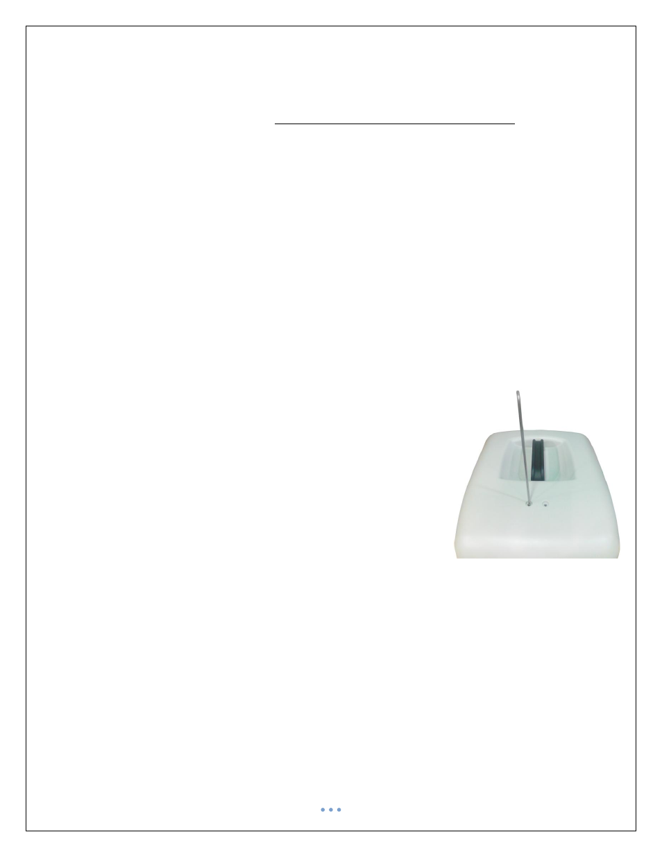
properly captured.
12. Insert an Alignment Tool thru hole in Top Cover and into mounting hole on
Sieve Bed Assy.
13. Ensure Top Cover is properly lowered and then remove the alignment tool.
14. Insert and secure Screw thru Top Cover and into opposite mounting hole on
Sieve Bed Assembly.
15. Remove Alignment Tool and insert second Screw thru Top Cover and into
remaining mounting hole on Sieve Bed Assembly and secure.
16. Secure Top Cover to Base using Hex Screws (x4).
17. Verify device is operating to specifications as described in the Final Test section
of this Manual.