86 10 a b – RISCO Group ZODIAC QUAD PIR User Manual
Page 2
Descripción general
El
ZODIAC QUAD con un elemento piroeléctrico
Quad Verdadero ha sido especialmente diseñado
para alta inmunidad a falsas alarmas y superior
desempeño de captura en aplicaciones residenciales
particularmente hostiles
La familia ZODIAC PRO incluye los modelos
siguientes:
◆
ZODIAC PRO: PIR de uso residencial con
excelente capacidad de captura e inmunidad a falsas
alarmas
◆
ZODIAC PET: PIR de uso residencial para
instalaciones que requieren inmunidad a animales
domésticos
Description Générale
La
ZODIAC QUAD, muni d'un capteur pyroélectrique
Quad, a été spécialement conçu pour optimiser la
définition de détection et étudié pour réduire
considérablement les fausses alarmes.
La famille des
ZODIAC PRO comprend également
les modèles suivants:
◆
ZODIAC PRO: Infrarouge passif pour les milieux
résidentiels avec une excellente performance de
détection et une réduction des fausses alarmes.
◆
ZODIAC AD: Infrarouge passif pour les milieux
résidentiels conçu pour permettre une parfaite
immunité aux animaux domestiques.
Descrizione Generale
Il rivelatore ZODIAC Quad, costruito con un Reale
elemento piroelettrico Quad, è stato specificamente
progettato per ridurre drasticamente gli allarmi impropri
senza rinunciare ad una efficace rivelazione in
applicazioni residenziali particolarmente critiche.
La gamma dei rivelatori ZODIAC comprende anche
i modelli seguenti:
◆
ZODIAC PRO: Rivelatore all’infrarosso passivo
con una eccellente qualità di rivelazione e immunità
ai falsi allarmi in ambienti residenziali
◆
ZODIAC PET: Rivelatore all’infrarosso passivo per
applicazioni residenziali, immune ai piccoli animali.
FRANÇAIS
ESPAÑOL
ITALIANO
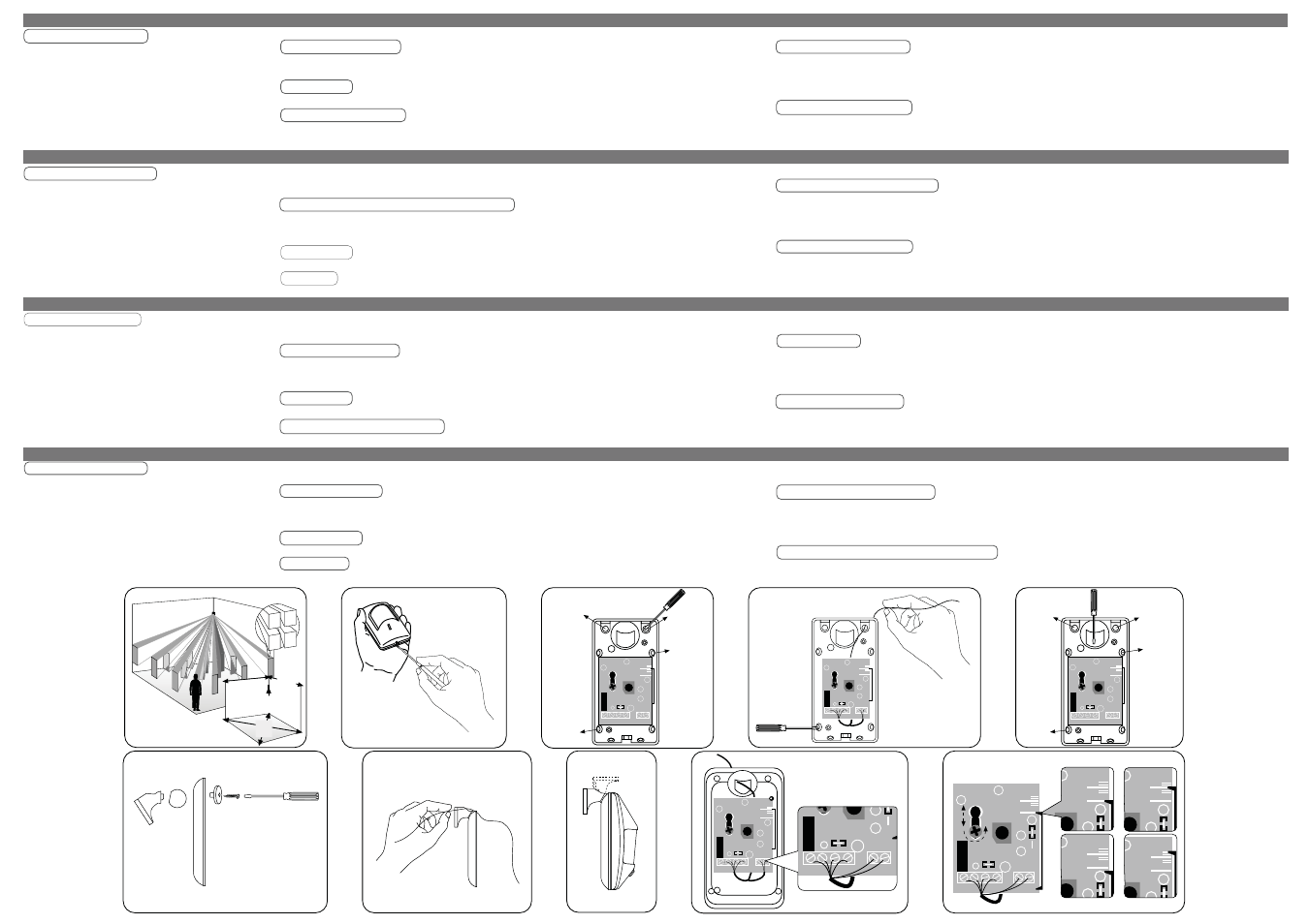
Posición de montaje
Consideraciones básicas: no instale el detector
expuesto directamente a la luz solar o cerca de
fuentes de calor (fig. 1).
Instalación
Abrir la cubierta (fig.2)
Procedimiento De Montaje
Sin dispositivo de montaje giratorio:
Abrir los agujeros pre-marcados para los tornillos de
montaje y la entrada de cables
CE-entrada de cables
MS-tornillos de montaje (fig. 3)
Le Meilleur Emplacement Pour L'installation
Considérations préliminaires
Ne montez pas le détecteur en exposition directe au
soleil ou près de sources de chaleur. (fig. 1)
Installation
Ouvrez le couvercle (fig. 2)
Montage
Sans la rotule :
Percez les pré perforations pour la fixation des vis
et le passage du câble.
CE - Passage du câble
MS - Vis de fixation (fig. 3)
Posizionamento
Considerazioni preliminari: non posizionate il
rilevatore rivolto direttamente verso la luce del sole
o in prossimità di fonti di calore (fig. 1)
Installazione
Aprite il Coperchio (fig.2)
Montaggio
Senza snodo:
Aprite i fori predisposti per le viti di fissaggio e il
passaggio cavi.
CE: Ingresso Cavo
MS: Viti di Fissagio (fig. 3)
Insertar los cables y fijar la base en su lugar (fig. 4)
Con dispositivo de montaje giratorio:
Abrir los agujeros pre-marcados para los tornillos de
montaje y la entrada de cables (fig. 5)
Fijar la base del detector al dispositivo de montaje
giratorio(fig. 6)
Insertar los cables en el detector (fig. 7)
Atornillar el dispositivo de montaje giratorio a la pared
o al techo (fig. 8)
Conecciones
12 VDC: Entrada de fuente de alimentación
ALARM: conmutador de Forma A (N.C.) relé
TAMPER: conmutador de Forma A (N.C.) relé
Faîtes passer le câble et fixez l’embase du boîtier à
son emplacement. (fig. 4)
Avec la rotule :
Perforez la pré découpe et percez les pré perforations
pour le passage du câble (fig. 5)
Emboîtez la rotule comme indiqué.( fig. 6)
Faîtes passer le câble dans le détecteur (fig. 7)
Vissez la base de la rotule sur le mur ou au plafond. (fig. 8)
Bornier De Raccordement
12VDC: Entrée alimentation
ALARM: Contact sec NF
TAMPER (autoprotection): Contact sec NF
Inserite il cavo e fissate la base nel corretto
posizionamento. (fig. 4)
Montaggio con snodo:
Premete sulle plastiche dei fori e rimuovete la plastica
dai fori per l’inserimento del cavo. (fig. 5)
Fissate la base allo snodo (fig. 6)
Inserite il cavo nel sensore (fig. 7)
Fissate la base dello snodo sulla parete o sul soffitto.
(fig. 8)
Rebouchez les trous restants avec du joint silicone. (fig. 9)
Ajustement De La Carte
Desserrez la carte en dévissant la vis de maintien. (fig. 10)
La position de la carte dépend de la lentille utilisée.
Lentille Grand Angle:
Hauteur de pose 2.5m
Position SHORT Taille de la pièce de 3 à 6
mètres
Position LONG Taille de la pièce de 6 à 12 mètres
Lentille Longue Portée:
18 mètres de portée Hauteur de pose 2.5m
Quand le détecteur est monté plus haut qu’à 2.5m
Quand le détecteur est monté plus bas qu’à 2.5m
(fig.10 a)
(fig.10 b)
(fig.10 b)
(fig.10 c)
(fig.10 d)
Sellar los agujeros (fig. 9)
Ajuste De La Tarjeta
Aflojar los tornillos sujetadores de la tarjeta.
Ajustar la posición de la tarjeta de acuerdo a la lente
utilizada
(fig. 10)
Collegamenti dei Morsetti
12VCC: Ingresso alimentazione
ALLARME: Normalmente chiuso (libero da tensione)
TAMPER: Normalmente chiuso (libero da tensione)
sigillare i fori del passaggio cavi (fig. 9)
Regolazione del Circuito Stampato
Posizionate il circuito secondo il tipo di lente
che utilizzate.
(fig. 10)
Grand’angolo:
Altezza: 2.5m
Dimensione della stanza: da 3 a 6m
Dimensione della stanza: da 6 a 15m
(fig.10 a)
(fig.10 b)
Lente per Portata Lunga:
Altezza: 2.5m
Portata: 18m
Posizionamento più alto dell’altezza normale
di montaggio.
Posizionamento più basso dell’altezza
normale di montaggio.
(fig.10 b)
(fig.10 c)
(fig.10 d)
ENGLISH
Mounting locations
Primary considerations (fig. 1). Do not mount the
unit in direct sunlight or near heat sources.
Installation
Open the cover (fig. 2)
Mounting procedure
Without swivel:
Remove knockouts for mounting screws and cable
entry
CE -Cable entry
MS -Mounting screws (fig. 3)
Insert cable and attach the base to location (fig. 4)
With the swivel:
Punch out Knockout.
Remove knockout for cable entry (fig. 5)
Attach base to swivel (fig. 6)
Feed the cable into the detector (fig. 7)
Wide angle:
Height 2.5m (8.2ft)
Room size: 3-6m (10-20ft)
Room size: 6-12m (20-40ft)
Long range lens:
Height 2.5m (8.2ft)
range 18m (59ft)
Higher than typical mounting heights
Lower than typical mounting heights
Screw swivel base on the wall or ceiling (fig. 8)
Terminal connections
12VDC: Power supply input
ALARM: NC dry contact switch
TAMPER: NC dry contact switch
Seal holes (fig. 9)
PC Board Adjustment
Loosen PC board holding screw
Position the board according to the lens used
(fig. 10)
(fig.10 a)
(fig.10 b)
(fig.10 b)
(fig.10 c)
(fig.10 d)
General Description
The
ZODIAC QUAD with Real Quad pyroelectric
element has been specially designed for high false
alarm immunity and high catch performance in hostile
residential environments.
The
ZODIAC PRO Family includes the following
models:
◆
ZODIAC PRO: Residential PIR with excellent catch
performance and false alarm rejection
◆
ZODIAC PET:
*
Residential PIR for pet immunity
installations
*
Not yet evaluated by UL
Lente gran angular:
Altura: 2.5m (8.2 pies)
Tamaño de habitación: 3-6m (10-20 pies)
Tamaño de habitación: 6-15m (20-50 pies)
Lente de largo alcance:
Altura 2.5m (8.2 pies)
Alcance: 18m (59 pies)
Alturas de montaje más altas que la típica
Alturas de montaje más bajas que la típica
(fig.10 a)
(fig.10 b)
(fig.10 b)
(fig.10 c)
(fig.10 d)
2
1
8.5m
28'
12m
40'
8.5m
28'
12m
40'
2.5m
8'2"
+
-
+
-
3
LONG
SHORT
ON OFF
LED
TAMPER ALARM
CE
CE
MS
MS
4
LONG
SHORT
ON OFF
LED
TAMPER ALARM
5
LONG
SHORT
ON OFF
LED
TAMPER ALARM
CE
CE
MS
MS
7
9
LONG
SHORT
ON OFF
LED
TAMPER ALARM
ON OFF
LED
TAMPER ALARM
12V
-
+
8
6
10
a
b
LONG
SHORT
LONG
SHORT
LONG
SHORT
LONG
SHORT
LONG
SHORT
ON OFF
LED
TAMPER ALARM
12V
-
+
c d