Back tamper terminal wiring, Dip switch settings – RISCO Group Wireless WatchOUT PIR WL T312 User Manual
Page 7
Installation Manual
7
English
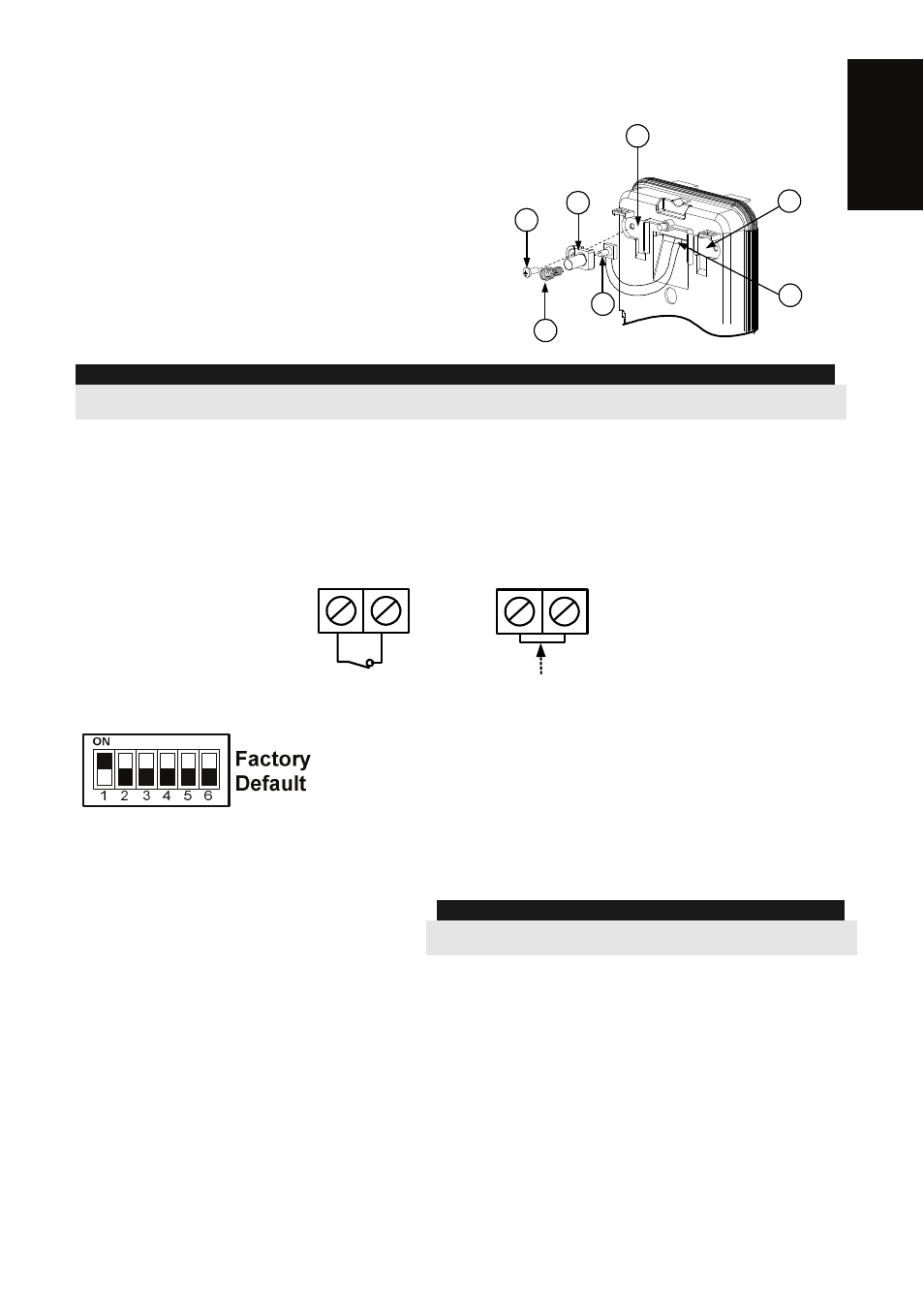
Changing Back Tamper position:
The back tamper is by default secured on the right
side of the internal base (Rear view). If you wish to
move it to the left side (rear view), do the following
(Figure 5):
1. Remove tamper screw 1 in order to release the
tamper from position 7.
2. Ensure tamper spring (2) rests over tamper wire
base 4.
3. Ensure plastic tamper bracket (3) rests over
both 2 and 4.
4. Secure tamper screw (1) into (3) over position 6.
Figure 5
Left Side
Tamper
Right
Side
Tamper
3
6
1
2
4
7
5
NOTES:
1.
Verify that you hear a "Click" when attaching the tamper spring to the wall.
2.
For pole installation, the tamper can be moved to the bottom right-hand side of the internal base.
Back Tamper Terminal Wiring
If you wish to use the back tamper (recommended) remove the short from the back tamper
terminal block and connect the back tamper wires to the back tamper terminal block.
Back Tamper in use
BACK TAMPER
Back Tamper not used
Short
H1
H1
DIP Switch Settings
DIP 1: LED operation
On: LED enabled
Off: LED disabled
DIP 2: PIR detection sensitivity
On: High
Off: Normal
DIP 3: Normal/Test modes
On: Test
Off: Normal
DIP 4: Not used
DIP 5: Not used
DIP 6: RF power
On: Low
Off: High
NOTE:
The DIP Switch needs to be positioned to OFF (High Power
position) unless sold in countries with FCC compliance.