Serial ports chapter 4 – Remote Processing RPC-52 User Manual
Page 12
SERIAL PORTS
CHAPTER 4
Page 10
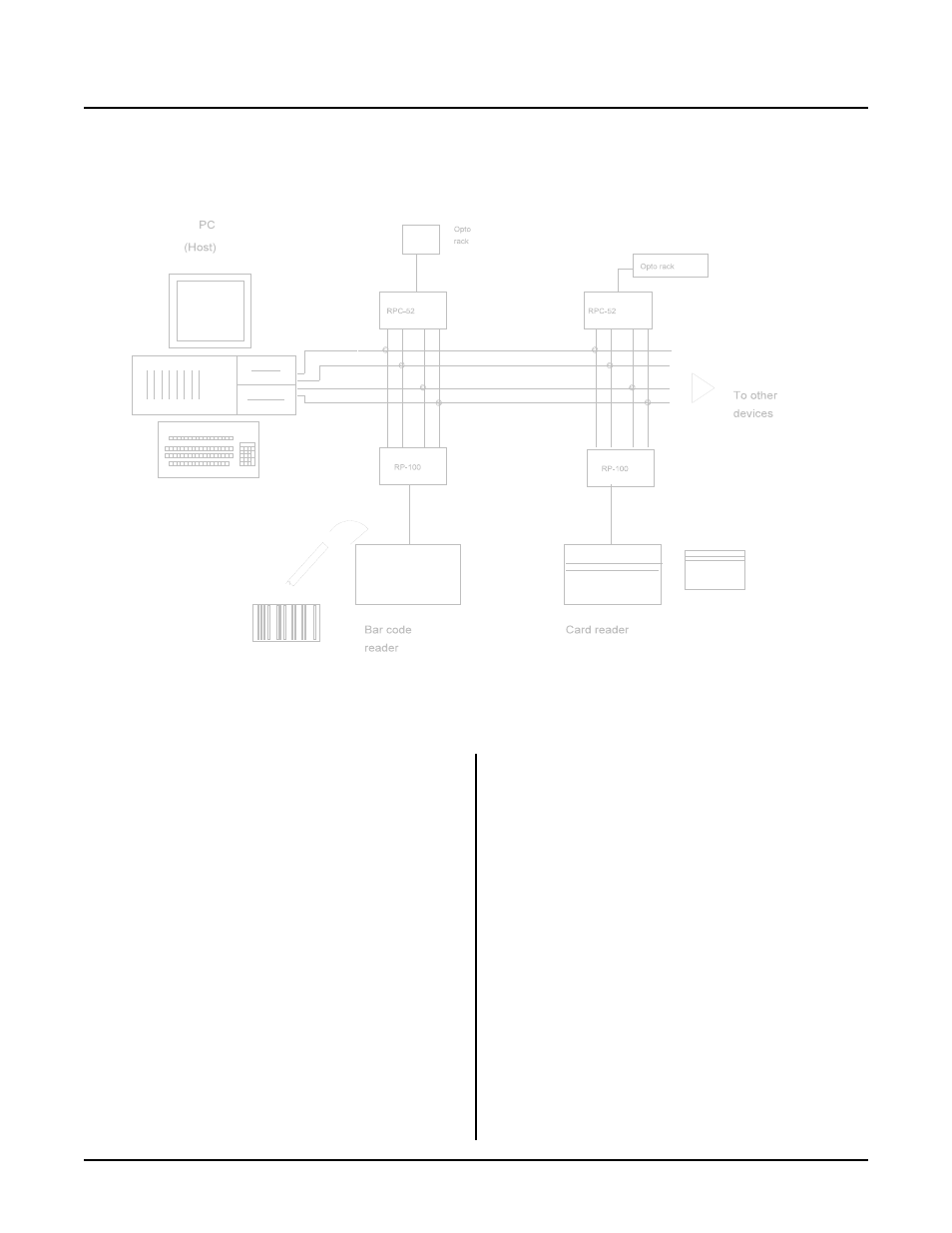
Figure 4-2 Network diagram
[1-3],[2-4]
Termination network installed
[3-5],[4-6]
Termination network removed
Only one slave device on a RS-485 network should have
a terminator installed. The host transmitter shou ld also
have a 100 ohm resistor in series with a 0.1 m fd
capacitor . T he term inator on the RPC -52 includes pu ll
up and pull down resistors to prevent lines from floating
and generating er roneous char acters.
TWO WIRE RS-485
The RS-485 port on the RPC-52 is set up for 4 wire
mode. 2- wire mode w ill cause the tra nsmitted da ta to
be received. T o use the RPC-52 is this mode, your code
should "flush" the received data or otherwise r emove
transmitted information.
Mechanically, to make a 2- wire system, simply connect
T+ to R+ and T- to R -. M ake sure CON FIG BAUD is
set up for RS-485 mode.
MULTIDROP NETWORK
You can use the RPC-52 in a m ultidrop network by
using CO M1' s RS-422/ 485 port. You can c onnect up to
32 units (including other RPC -52' s) over a 4,000 foot
range.
Figure 4-2 shows an exam ple of a multidrop network.
This networ k includes a host and one or m ore devices.
The host transmits data packets to all of the devices, or
nodes, in the network. A data packet includes an
address, com mand, data, and a checksum. See figure 4-
3. The packe t is received by all devices, and ignored by
all except the one addressed.
The relationship described below between nodes and the
host is a maste r-slave. The host dir ects all
c o mm u ni ca ti on . N o de s " d o n o t s pe a k u n le ss sp o ke n to " .
Peer to peer com munication, while possible with the
RPC-52, is not discussed here.
Ther e are m any com municatio n protoco ls. F or this
example, a protocol might look som ething like this: