Chapter 9 keypad port – Remote Processing RPC-2350 User Manual
Page 50
CHAPTER 9
KEYPAD PORT
9-1
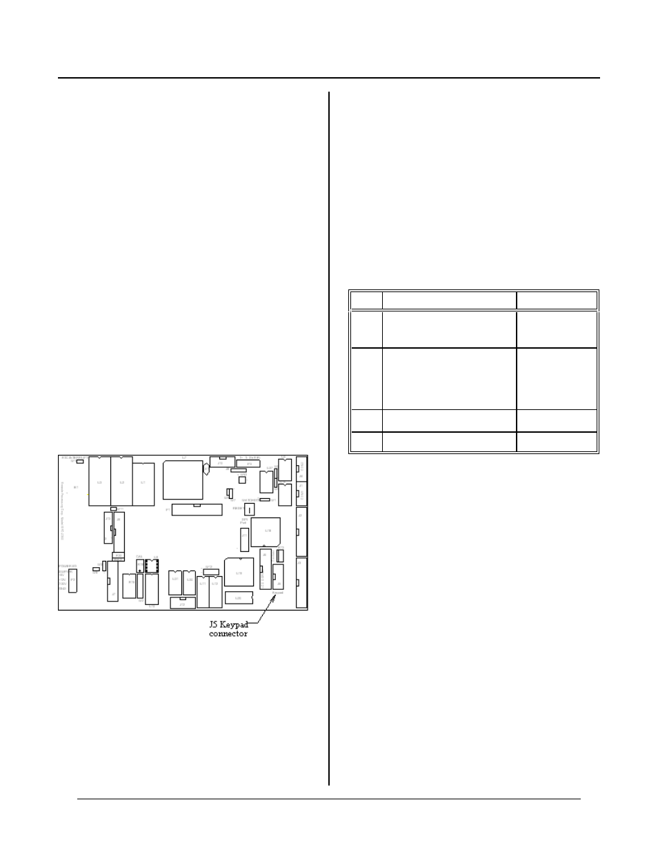
Figure 9-1 J5 keypad connector location
CHAPTER SYNOPSIS
Operating information
Multiple us e note
DESCRIPTION
KEYPAD PORT C HAPTER 9
16 position keypads are plugged into keypad port J5.
Keys ar e arr anged in a 4 x 4 to 6 x 4 matr ix form at. A
key is rec ognized w hen a ro w and a co lumn con nect.
Up to 24 keys can be scanned.
CAMBASIC scans and debounces the keypad every
debounce time. Debounce time is fixed at 40 ms. A key
is debounced when it is down for two scans (80 ms).
Keypad presses may be returned either as a num ber from
1 to 16 (1-24 in 24 position scan mode)or as an ASCII
charac ter. The A SCII cha racter retur ned cor respond s to
those on Remote Processing's KP-1 keypad. Char acter
assignments are changed using the SYS(8) function.
Keypads from Rem ote Processing simply plug into J5.
Keypad ca ble length should be limited to 5 fe et.
If the keypad port is not used, it may be used as a
genera l purpose digital I/O port.
When 24 keys are scanned, U19 port B bits 0 and 1 are
used for scanning. These lines also go to the high
current buffer U 20, and on to J3, pins 8 and 10. If you
are using the high current port also, do not use these two
lines.
PROGRAMMING THE KEYPAD
Sixteen and 24 position keypads use all of port C at U19.
The 24 position keypad use and additional 2 lines from
port B. Por t B drives the high current sink, U20. If you
are using the high cur rent dr iver, or have replace d it
with a DIP shunt jumper, lines at J3-8 and J3-10 are not
usable with a 24 position keypad only.
U19 (keypad port IC) m ust be configured using the
CON FIG PIO c omm and. Some po rts are optional,
depending upon what you want to connect to it. Use the
table below to help determine what a port should be
(input or output) when using a keypad.
Port
Function
Configuration
A
LCD char acter driver
G e ne r al pu r po se T T L I/ O
Output
Output or input
B
High current sink
When using 24 keypad
Use 16 position keypad or
g e ne r al pu r po se T T L I/ O
Output
Output
Output or input
LC
Keypad row (inputs)
Input
U C
K e yp a d c o lu m n
Output
Check the table above to determine what you will be
using. The Configuration column describes what that
port should be set to.
The ON K EYPA D$ multitasking statement initializes the
operating system to use the keypad. It tells the system
what size of keypad to scan and what line to execute on a
key press. W hen this command is executed, the
scanning process beg ins.
INPU T KEYP AD$ allow you to input data from the
keypad and echo the data to an LCD chara cter or
graphics display. Input can be a string or floating point
number. Refer to INPU T KEYP AD$ com mand in the
CAMBASIC manual. Use 8 for echo port. Only smaller
characters can be echoed back to the display.
The KEYPA D$(n) function returns either the keypad
character (as an ASCII value) or its position. When
getting a character, keep in mind the difference between
an ASCII value vs real. An ASCII ‘1' is not the same as
the number 1 used for calculations.