Reset ddc table to default values, Color depth selection, Selecting moment of switching to next frame – Rose Electronics CrystalView DVI CATx User Manual
Page 19
CRYSTALVIEW DVI CATx INSTALLATION AND OPERATIONS MANUAL
13
Reset DDC table to default values
To reset the DDC information to the factory default values, perform the
following steps:
1. Remove power from the Local unit and remove the cover
2. Remove jumper JP1 (see internal PC board figure)
(JP1 and JP2 open)
3. Switch on the power to the Local unit
4. The Local Unit’s Video OK LED will blink rapidly for approximately
1 second upon successful re-programming of the default DDC values
5. Remove power from the Local unit
6. Replace jumper JP1, replace the cover, and power on the Local unit.
The DDC table now contains the default factory settings.
(NOTE: On the dual model, both upper and lower PC board’s jumper JP1
must be removed)
Color Depth Selection
The CrystalView DVI CATx allows you to select the color depth desired. You
can select 18 Bit (256K) or 21 Bit (2M) color. The change the default setting
of 18 Bit to 21 Bit, perform the following procedure on the LOCAL unit.
1. Remove power from the Local unit
2. Remove the cover
3. Remove jumper JP3 (see below table)
4. Replace the cover and power on the Local unit.
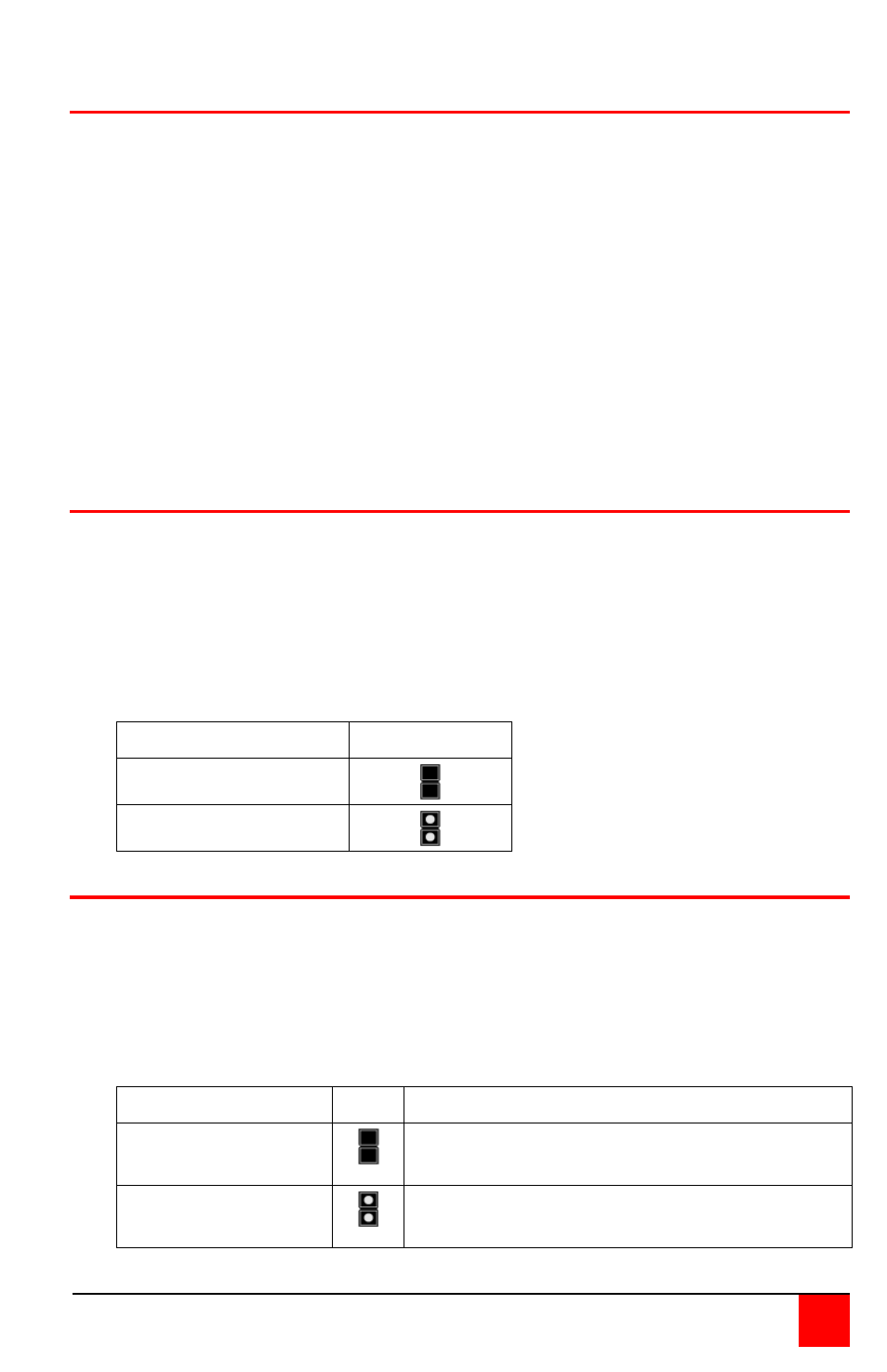
Color Depth
JP3 setting
18 Bit (default)
21 Bit
Selecting moment of switching to next frame
Normally the transmission of screen data is terminated when a frame is
displayed on the screen. If the video source switches to a new frame during
this display period, horizontal screen breaks may be seen.
Jumper JP3 on the Remote unit’s PC board can be set to change the moment
of switching. Remove the cover on the Remote unit and set JP3 accordingly.
Moment to switch JP3 Description
Switch during
HSYNC (default)
Higher frame rate but may produce
detectable horizontal breaks
Switch during
VSYNC
Lower frame rate but may produce
stepping pictures (no horizontal breaks)