Switched mode examples, Rgb settings in fixed mode, Rgb settings in switched mode – Rosen Aviation 0700-006 : Video Distribution Amplifier User Manual
Page 8
Rosen Aviation
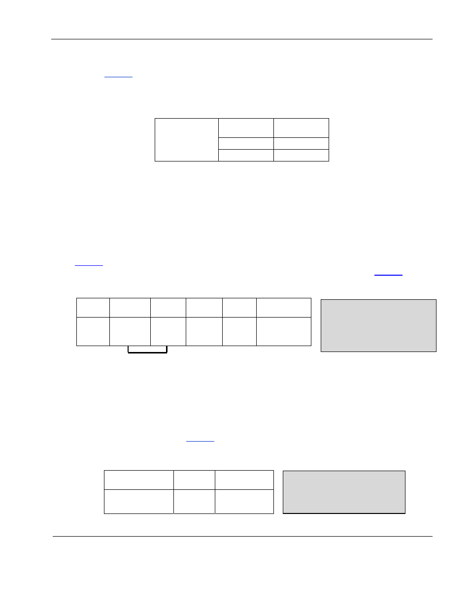
4.2.1. RGB Settings in Fixed Mode
shows the configurations for an RGB video output in fixed mode. Typically you
use input source B for fixed mode and input source A for switched mode.
Table 3 Fixed mode example: One RGB video source and no source select switch
RGB
Output 1
Mid DIP
SW9
RGB Source
OFF
A
ON
B
To configure RGB outputs 2 and 3, set Mid DIP SW10 and SW11 to the desired
source.
4.3. Switched Mode Examples
Source select is an externally wired control that enables you to select different video sources of
the same type. The Video Distribution Amplifier switches between composite sources or RGB
sources, but it does not switch between the two.
shows how to configure a composite output to receive four inputs with a source select
switch. For an example with RGB input sources and a source select switch, see
Table 4 Switched mode example: Four composite video input sources (A-D) using a source select switch
Left DIP
SW1
Left DIP
SW2
Mid DIP
SW7
Mid DIP
SW8
Composite
Source
Comp
Output
1
OFF
OFF
N/A*
ON
A, B, C, & D
Switched mode will always use the
OFF/OFF combination
To use composite select
switches, connect the
switches to pins 1-8 and
corresponding Return pins
10-17 on the P2 connector.
*SW7 can be set to either OFF or ON to enable source D.
4.3.1. RGB Settings in Switched Mode
If you use two RGB video sources and a source select switch, configure the DIP
switches as shown in
Table 5 Switched mode example: Two RGB video sources using a source select switch
To use RGB select switches,
connect the switches to pins 3-5
and corresponding Return pins
14-16 on the P5 connector.
Mid DIP
SW9
RGB Source
RGB
Output 1
OFF
A & B switched
To configure RGB outputs 2 and 3, set middle DIP SW10 and SW11 the same way.
Document Number: 101720
Revision: A
Date: 10/14/08
Template: 4.2.3-6-FM; Revision A; 16 May, 2005
Page 8 of 16