Additional ventilation – SAF OPAL LT User Manual
Page 5
Installation Notes
4
Prior to Installation
Check that Motor's Full Load Ampere (FLA) is lower
than or equal to starters Full Load Current (FLC) and
that Mains voltage is as indicated on the front panel.
Mounting
X 3
RVS-AX
M
C/T
C/T
• The starter must be mounted vertically. Allow
sufficient space above and below the starter for
suitable airflow.
• It is recommended to mount the starter directly on
the rear metal plate of the switchgear for better
heat dissipation.
• Do not mount the starter near heat sources.
• Protect the starter from dust and corrosive
atmospheres.
Temperature Range and Heat Dissipation
The starter is rated to operate over a temperature range
of –10ºC (14ºF) to +40ºC (104ºF).
Relative non-condensed humidity inside the enclosure
should not exceed 93%.
The heat dissipation during continuous operation is
Approx. 0.4 x In (in watts).
Example
: When motor's current is 100 Amp, heat
dissipation will be approx. 40 watts.
Internal enclosure heating can be reduced using
additional ventilation.
Additional Ventilation
RVS-AX
General purpose enclosure
with filter on the air inlet and
Fan on air outlet.
RVS-AX
Fan, creating air circulation
Voltage Spike Protection
Voltage spikes can cause malfunction of the starter and
damage the SCRs. When expected, use suitable
protection such as Metal Oxide Varistors (consult
factory for further details).
Short Circuit Protection
The RVS-AX should be protected against a short
circuit by Thyristor Protection fuses.
The recommended I
2
t values are:
RVS-AX type
I²t (A²S)
Ferraz Fuses
RVS-AX 8
400
6,6 URS 35
RVS-AX 17
2,000
6,6 URS 45
RVS-AX 31
3,000
6,6 URS 63
RVS-AX 44
6,000
6,6 URB 100
RVS-AX 58
12,000
6,6 URB 150
RVS-AX 72
18,000
6,6 URB 160
RVS-AX 85
40,000
6,6 URD 200
RVS-AX 105
60,000
6,6 URD 250
RVS-AX 145
100,000
6,6 URD 355
RVS-AX 170
140,000
6,6 URD 400
Caution
Power factor correction capacitors must not be
installed on starter's Load side. When required,
Install capacitors on the Line side.
Warning
When Mains voltage is connected to the starter,
even if start signal has not been initiated, full
voltage may appear on the starter’s load
terminals. Therefore, for isolation purposes it is
required to connect an isolating device (C/B,
switch, line contactor, etc) upstream to the RVS-
AX (on the Line Side).
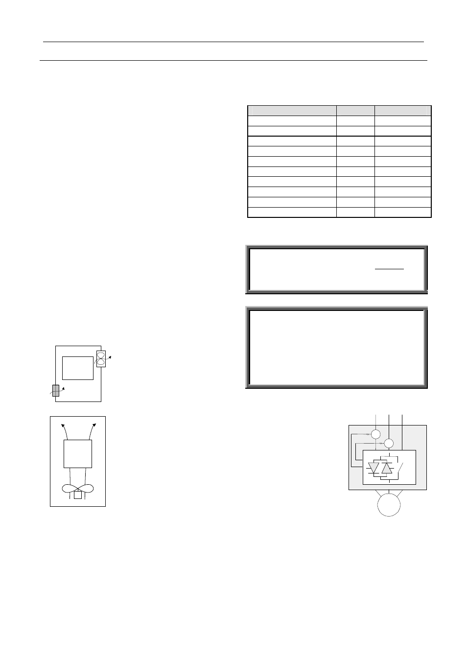
Built-in Bypass
The RVS-AX incorporates
internal bypass relays
allowing current flow
through the thyristors only
during starting process. At
the end of the starting
process, the built-in relays
bypass the thyristors and
carry the current to the
Motor.
Upon stop signal, or in
case of fault, all three
bypass relays will open and stop the motor.
When Ramp-Down potentiometer is set to allow soft-
Stop process, upon stop command, the bypass relays
will open immediately and the current will flow
through the thyristors. The voltage will then be
reduced slowly and smoothly to zero.