Pc-tft-35xs-led – Purdy AND-TFT-35XS-LED-KIT User Manual
Page 6
PC-TFT-35XS-LED
Purdy Electronics Corporation • 720 Palomar Avenue • Sunnyvale, CA 94085
6
Tel: 408.523.8200 • Fax: 408.733.1287 • [email protected] • www.purdyelectronics.com
1/15/09
T
e
r
Pin
No.
Symbol
I/O
Description
Remarks
1
+5V
O
5.0V output
–
2
COL
I
color adj.
–
3
BRT
I
brightness adj.
–
4
CNT
I
contrast adj.
–
5
Video
I
composite video signal
The signal resistance is 75
Ω
, 1V p-p.
6
U/P
I
up/down scan control
+5V or GND
7
R/L
I
left/right scan control
+5V or GND
8
GND
I
ground
–
9
GND
I
ground
–
10
+12V
I
+12V DC power input
–
11
HSY
O
HSY output
–
12
VSY
O
VSY output
–
Connector:
Pin No:
FC12D (Bottom Contact)
Pitch:
FC 1.0mm
Output Characteristics:
DC to DC Backlight Inverter:
Starting Voltage
: 15.8VDC, typical at 6.0 VDC
Working Voltage:
16.0 VDC, typical at 15 VDC
Working Current:
DC 10mA ± 20% typical for general application.
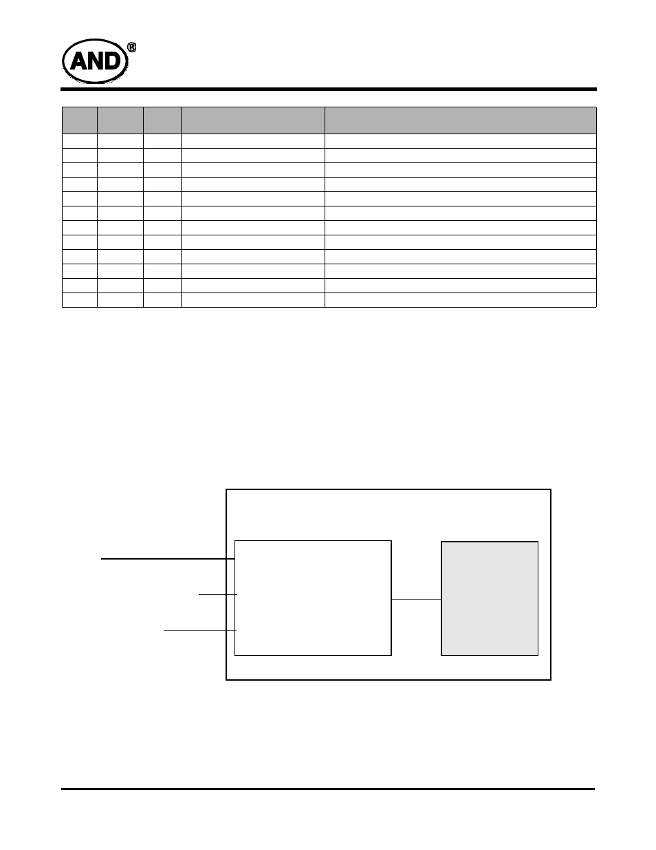
Block Diagram
Power
Composite Video/RGB Signal
Picture control signal
Video Chroma Signal
Processing
DC/DC – LED Driver
AND-TFT-35XS-LED
AND-TFT-35XS-LED PC-TFT-35XS-LED