Displays, Connector pin assignment for interface – Purdy AND3222MST2 User Manual
Page 4
Advertising
Purdy Electronics Corporation • 720 Palomar Avenue • Sunnyvale, CA 94085
4
Tel: 408.523.8200 • Fax: 408.733.1287 • [email protected]
7/20/07
www.purdyelectronics.com
Displays
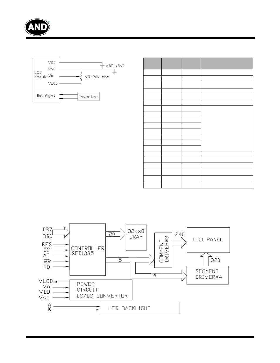
Connector Pin Assignment for Interface
Power Supply
Interface Pin Assignment
Terminal
No.
Symbol
Level
Function
1
V
SS
0V
Power Supply Ground
2
V
DD
5V
Logic Supply Voltage
3
V
O
–
Contrast Adjustment Voltage
4
/RD
L
Read Signal
5
/WR
L
Write Signal
6
Ao
H/L
Data Type Select
7
DB0
H/L
Data Bus Line
8
DB1
H/L
9
DB2
H/L
10
DB3
H/L
11
DB4
H/L
12
DB5
H/L
13
DB6
H/L
14
DB7
H/L
15
/CS
L
Chip Signal
16
/RST
L
Reset Signal
17
V
LCD
–
Power Supply for LCD
18
FG
–
For GND
19
NC
–
No Connection
20
NC
No Connection
Block Diagram
AND3222MST2
Advertising