Installation – DE DIETRICH WBD1211 User Manual
Page 22
Recommendations regarding
the construction and fitting of
a base when the installation
requires an integrated
appliance to be raised
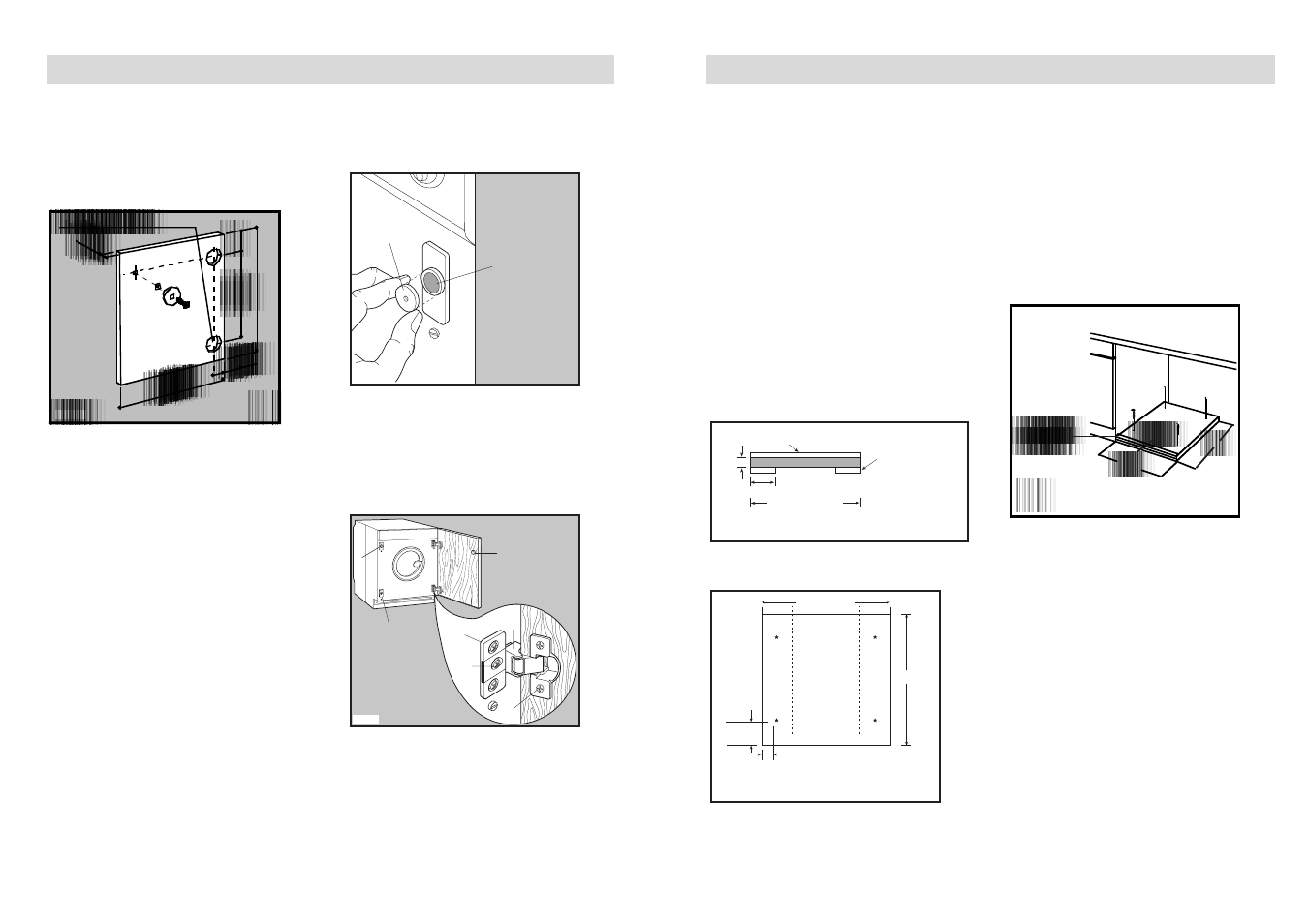
Where the appliance has been raised by
mounting onto a wooden base provided
by the installer. The material used to
construct the base should have a non
slip surface, be water repellent and if
possible be one solid piece.
If it is not possible to use one solid
piece, due to the additional height
required, ensure that any additional
strips of timber are glued and screwed
to the underside of the base (see Fig. F).
Drill four fixing holes (see Fig. G)
600-605 mm
50 mm
Front edge
Top view
95 mm
490 mm
G
600-605 mm
Front view
5 mm Hardwood strip
Additional pieces of
timber should run
from front to back
100 mm
40 mm
F
Position the base into the recess with its
front edge as far forward as the
adjoining plinth line will allow. The
reason for placing the base in this
position is to allow a small strip of
beading to be fitted in front of the
appliance feet.
Fix the base firmly to the floor using four
appropriate countersunk screws (see
Fig. H).
With the appliance installed adjust all
four feet ensuring the machine is stable,
and a clearance of approximately 5 mm
is left between the top of the machine
and the underside of the worktop.
A final check for stability should be
carried out with the machine on spin
with a load, this will identify the need for
any further fine adjustment to the feet.
A strip of beading approximately
605 mm W, x 5 mm H, x 25 mm D must
be screwed down into the base directly
in front of the machine’s feet, this will
provide additional security.
If required an additional door magnet,
part number 1242394-00/3 and disc,
part number 1242393-00/5 are available
from spare parts.
43
Installation
The required dimensions are given in
the picture C.
The hinges will be fixed to the door by
means of screws for wood (2-Fig. B)
supplied with the appliance.
c) Mounting the door
Fix the hinges (1) to the machine by
means of the M 5x9 screws (3-Fig. B).
The hinges can be adjusted to
compensate for possible uneven
thickness of the door.
To align the door perfectly it is
necessary to loosen the screw (3-Fig.
B), adjust the door and tighten the
screw again.
d) Counter-magnet (6)
The appliance is pre-arranged for a
magnetic closure of the door. To
enable a correct operation of this
device, it is necessary to screw the
counter-magnet (6) (steel disk +
rubber ring) into the inner side of the
door.
Its position must correspond to the
magnet (4) on the appliance (see
picture D).
If the door has to be opened from left
to right, invert the position of the
plates (7), the magnet (4) and the
plates (5) (Fig. B and E). Mount the
countermagnet (6) and the hinges (1)
as previously described.
4
6
5
1
2
3
7
E
P0983
P0984
6
4
D
42
Installation