Amprobe RS-3 Rotary-Scale-Clamp-On User Manual
Page 2
PRECAUTIONS FOR PERSONAL
AND INSTRUMENT SAFETY.
IMPORTANT:
1. Read these instructions thoroughly and follow them carefully.
2. In any instances, you will be working withdangerous levelsofvoltage
and/or current, therefore, it is important that you avoid direct contact with
any uninsulated, current-carrying surfaces. Appropriate insulating gloves
should be worn.
3. Before connecting or disconnecting the voltmeter to or from the circuit to
be tested, turn off power to the circuit.
4. Before applying test leads to circuit under test, make certain:
a. Proper test leads are plugged into correct instrument jacks, and
b. Selector switch is set to proper range.
5. Before using any electrical instrument or tester for actual testing,
the unit should be checked on a known Iive line to make certain it is
operating properly.
6. Make certain no voltages is present in circuit, before connecting ohmme-
ter to circuit.
7. The jaws of clamp-on instruments Should not, under any circumstances,
be used as a device to hold or hang the instrument. When using the
instrument as a voltmeter or ohmmeter, never clamp the jaws around on
to a conductor box or anything else - conducting or non-conducting. For
easier and faster voltage and resistance tests, we recommend Extendo
Leads, available from your AMPROBE distributor.
8. When measuring voltage or current with models that have an ohmmeter,
remove the ohmmeter battery/fuse attachment from the instrument.
Under no condition must the ohmmeter battery/fuse attachment be left
plugged in whendoingampsorvoltsmeasurement.Usetheohmmeter
battery/fuse attachment only when taking resistance measurements.
9. When making ohms measurement, be sure that theohmmeter attachment
is model OHB-3HE. This is the only attachment that should be used with
the
RS-3.
10. Failure to follow these precautions, can result in instrument damage and
or personal injury.
11. Before interpreting a reading on the Instrument be sure that the Pointer
lock is free or in the off position. The pointer is free when button is at
left position (See Fig. 2).
ZERO ADJUSTMENT
For greater accuracy, the pointer should
be set on the zero line. This is done with
the zero adjustment screw. If while turn-
ing the zero adjust screw, the pointer
swings away from the zero line, and will
not come to reset directly over it, it is
possible that the scale window is stati-
cally charged. To neutralize - clean win-
dow with fluid from SCK-100 Anti Static
Cleaning Kit.
2. Turn rotary scale selector until
highest current range appears in
window
3. Press trigger button to open Jaws
4. Encircle one conductor with the
Transformer Jaws
5. Release finger pressure on Trigger
toallowProbeJawstoclose around
the conductor before attempting to
read the meter
6. If pointer indicates
below 40 Amps
(Fig 5)
DON'T READ
YET
!
IMPORTANT
READ “Precautions for Personal and Instrument Safety”
before using instrument.
HOW TO TAKE CURRENT READINGS
(See Pages 2 and 5 for range-expanding accessories)
(All ampere ranges are printed black)
7. Set Rotary scale
selector to next
current range
until a reading is
obtained in the
upperhall of scale.
8. If the reading is below half scale on the lowest range of the
meter and greater accuracy is desired either one of the foll-
owing methods can be used
a. Loop the Conductor two or more 1,me, around the trans
former laws and divide the reading by the number at turns.
b. Use the AMPROBE Energizer. It increases current measur-
ing sensitivity 10 times 0-6 amp range becomes 0-0 6 amps.
Can also be used to take voltage measurements at recepta-
clesunderloadconditions.EnergizerGroundAdapter A D P46,
available separately as an accessory enables A-47Lto be
used for taking current measurements on 115VAC/15Amp
equipment with ground plug while maintaining existing
equipment ground circuit! See Fig 7
1. Make certain pointer Locks is in “OFF” position.
Rotary
Scale
Selector
Ground Adaptor ADP-46
Fig. 2
Fig. 7
Energizer model A-47L
Fig.1
PAGE 1
PAGE 2
PAGE 3
Pointer
Lock
Button
Zero
Adjust
Screw
HOW TO TAKE VOLTAGE READINGS
(All voltage ranges are printed red )
1. Insert bayonet type voltage test leads
into Voltage replacements at bottom of
instrument. Push against receptacle
spring and twist to lock in place (Fig 8)
2. Turn Rotary Scale Selector until highest
voltage range -600 volts-appears
in window.
3. Connect one alligator Clip to one side of
line. Then with meter in one hand, touch
the other side of the line with the other
alligator clip. If voltage does not exceed
600 volts, attach second alligator clip and
read voltage on red scale.
4. If voltage does not exceed 300 volt, turn
rotary scale selector clockwise until the
300 volt range is visible.
5. If voltage does not exceed 150 volt, turn
rotary scale selector clockwise once
more until 150 volts scale is visible
in window.
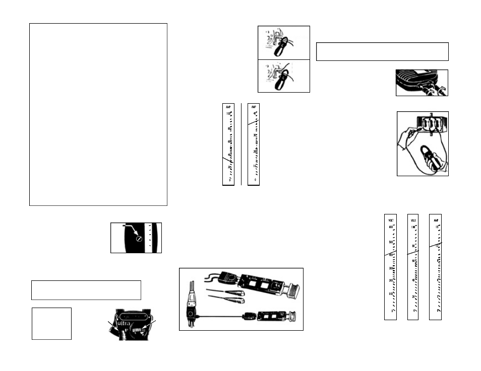
HOW TO READ THE SCALE
Let assume the pointer is at the position indicated in the illustra-
tion. The reading will be as follows, depending on the setting of
the range selector.
Fig.10
Pointer Reads 440 Volts. Each
between 400 & 500 is
is 20 volts.
Fig.11
Pointer Reads 78 Amps. Heavy
mark between 60 & 80 is 70 amps.
Each subdivision between 60 & 80
is 2 amps.
Fig.12
Pointer reads 12.7 Amps. Heavy
mark above 12 is 13 amps. Each
subdivision between 12 & 15 is 5
amp.
Pointer is free when
button is at left.
TO PREVENT DAMAGE
TO INSTRUMENT D O
N O T S TORE IT W I T H
POINTER IN LOCKED
POSITION.
Fig. 5
Fig. 6
Fig. 8
Fig. 10
Fig. 11
Fig. 12
Fig. 9
Both conductors
WRONG!
Try it
again
Fig 3
Fig 4
Right!
watch
the pointer
IMPORTANT:
Read “Precautions for Personal and Instrumental Safety”
before using instrument.
80
60
40
.
.
.
.
.
.
.
.
.
.
.
.