2 of 3 – Avago Technologies MegaRAID SATA 300-8XLP User Manual
Page 2
2 of 3
describes the jumpers and the connectors
on the MegaRAID SATA 300-8XLP.
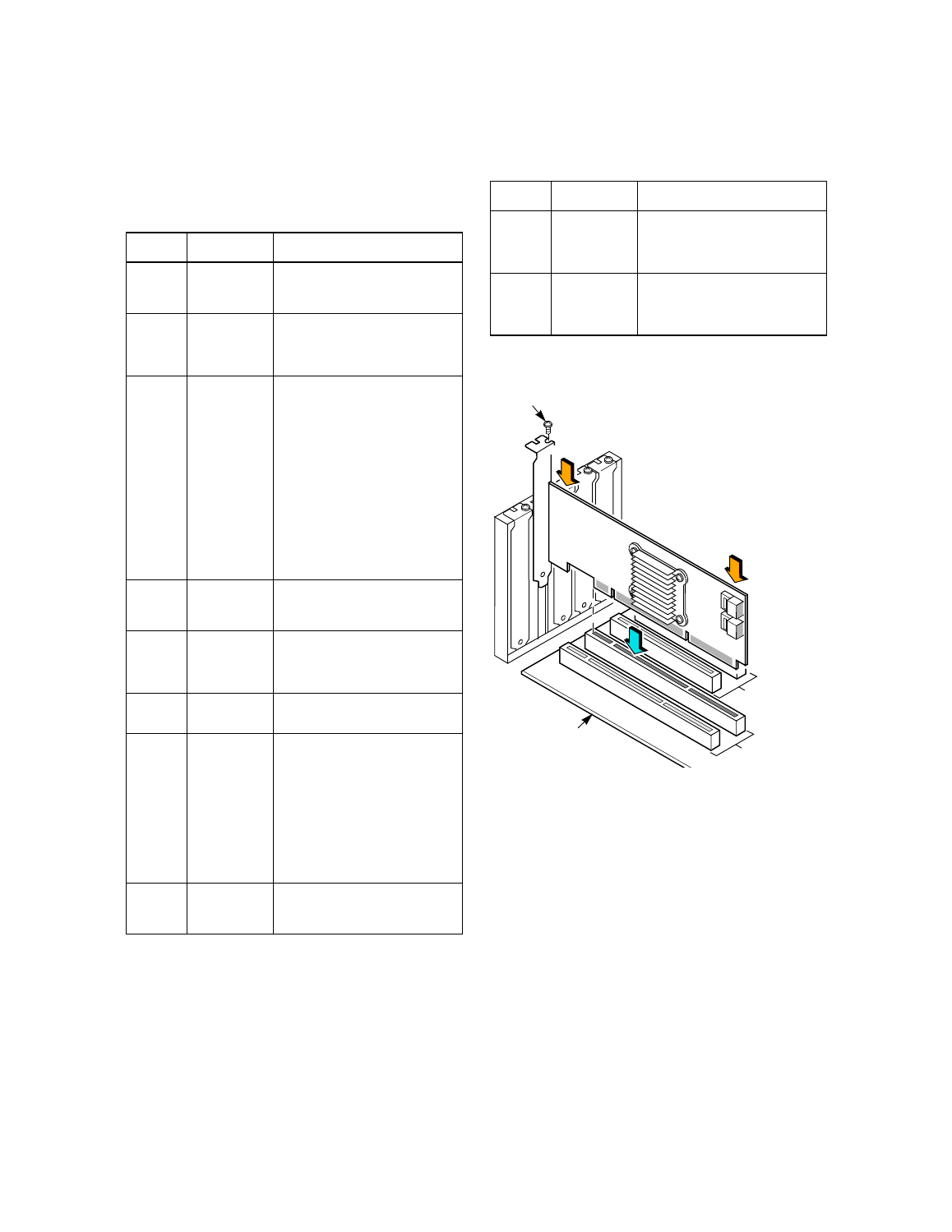
Figure 2 Installing the MegaRAID SATA 300-8XLP
RAID Controller
Step 4
Install the MegaRAID SATA 300-8XLP
Insert the MegaRAID SATA 300-8XLP in a PCI-X
slot on the mainboard, as shown in
.
Press down gently but firmly to seat the card
properly in the slot. Secure the RAID controller to
the computer chassis with the bracket screw.
Note:
Refer to your mainboard guide for information
about the PCI-X slot.
Step 5
Configure and Install the SATA Devices in the
Host Computer Case
Refer to the documentation for the SATA devices
for any pre-installation configuration
requirements.
Table 1
MegaRAID SATA 300-8XLP Card Layout
Jumper/
Connector Description
Type
J1
Battery Pack
connector
20-pin connector.
Provides interface to the remote
battery pack.
J2
LED SATA
Activity
connector
2-pin connector.
Provides LED interface to indicate
SATA activity on one or more SATA
drives.
J3
Firmware Initial-
ization Mode
Select
2-pin connector.
If the firmware flashed onto the board
is corrupted, you must install a jumper
on J3 (this holds the CPU core in
reset), so that you can flash the firm-
ware. Remove the jumper after you
flash the new firmware.
No jumper: This is the setting during
normal operation (Mode 3). This is
the default.
Jumper: This holds the CPU core in
reset (Mode 0).
1.
The card does not function as a
RAID controller if this jumper is
mounted.
J4
I
2
C Interface
3-pin connector.
Communicates with storage
enclosure processor (SEP) devices.
J5
SATA 300-8XLP
Ports
Ports 4–7.
These ports connect the cables from
the adapter to the SATA physical
drives.
J6
Serial Port
RS232
Debugger
4-pin jumper.
Used for diagnostic purposes.
J7
BIOS Enable
header
2-pin header.
The BIOS function is enabled or dis-
abled in software depending on the
status of this jumper.
No jumper: BIOS is enabled. This is
the default.
Jumper: BIOS is disabled.
2.
The card does not function as a
RAID controller if this jumper is
mounted.
J8
SATA 300-8XLP
Ports
Ports 0–3.
The ports connect the cables from the
adapter to the SATA physical drives.
J9
LED SATA
Activity Interface
connector
16-pin (8x2) jumper.
Provides LED interface individually to
eight SATA ports. The LED indicates
SATA activity on specific ports.
J10
LED Drive Fault
Interface
connector
16-pin (8x2) jumper.
Provides an LED interface individually
to eight SATA ports. The LED indi-
cates a drive fault on specific ports.
Table 1
MegaRAID SATA 300-8XLP Card Layout
Jumper/
Connector Description
Type
32-bit Slots
64-bit Slots
(3.3 V)
(3.3 V)
Edge of
Mother Board
Bracket Screw
Press Here
Press Here