Quick hardware setup guide, Page 2 – Avago Technologies MegaRAID SCSI 320-2E User Manual
Page 2
Page 2
Quick Hardware Setup Guide
The following diagram shows the location of the jumpers and
connectors on the MegaRAID SCSI 320-2E Controller.
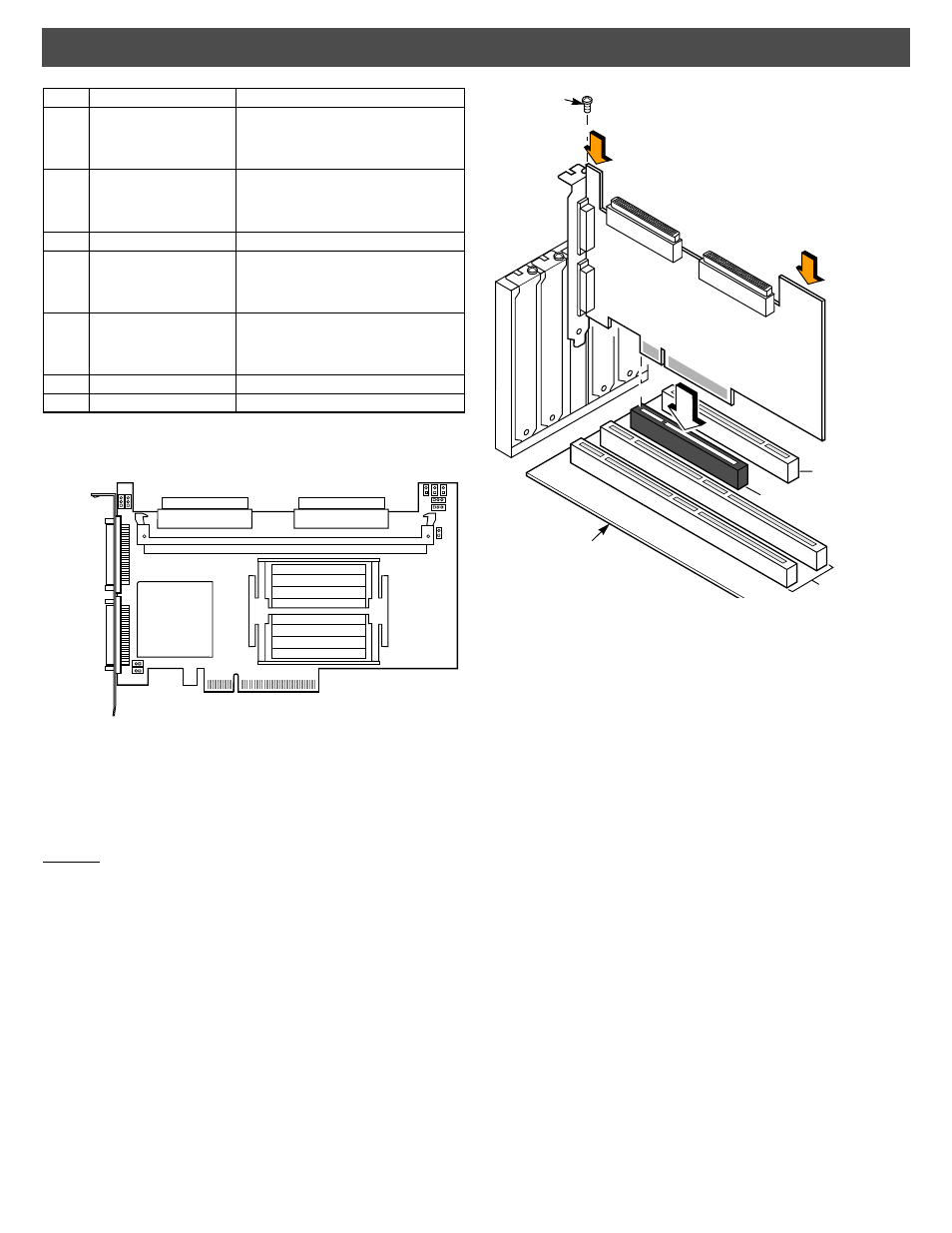
Step 4: Install the MegaRAID SCSI 320-2E Controller
Install the MegaRAID SCSI 320-2E Controller in a PCI-Express slot,
as shown in the following figure. Press down gently, but firmly, to make
sure that the card is properly seated in the slot. The bottom edge of
the controller card must be flush with the slot. Attach the MegaRAID
SCSI 320-2E to the computer chassis with the bracket screw.
Caution: If your board has a memory module, never apply
pressure to the module when inserting the adapter.
Applying pressure could break the module.
Step 5: Connect SCSI Devices to the MegaRAID Controller
Connect SCSI devices to the internal, high-density, 68-pin SCSI
connectors (J9 and J10) and/or the external, very-high density,
68-pin SCSI connectors (J12 and J14). To achieve maximum data
throughput, use only Ultra320 SCSI devices. The MegaRAID SCSI
320-2E Controller supports up to 30 Ultra320 SCSI devices at a
maximum SCSI bus cable length of 12 meters. You also can
connect Ultra160 and Ultra2 SCSI devices. The MegaRAID 320
Storage Adapters User’s Guide lists the maximum number of
devices and maximum cable length for each SCSI device.
Disable SCSI termination on all devices that are not connected at
the end of the SCSI bus. Use only high-quality ribbon SCSI cables
for internal devices and high-quality round SCSI cables for
external devices.
Step 6: Set the Target IDs for the SCSI Devices
Each connected SCSI device must have a unique Target ID (TID),
ranging from 0 to 15 for 16-bit devices. Note that under the DOS
Advanced SCSI Programming Interface, SCSI devices are limited
to SCSI IDs 0–6. The MegaRAID SCSI 320-2E Controller is
automatically assigned TID 7, which has the highest priority. Verify
that no two SCSI devices are set to the same TID. Change the TIDs
as needed. Refer to the SCSI device documentation if you are not
sure how to do this.
Step 7: Set SCSI Termination
The SCSI bus, which consists of connected SCSI cables and SCSI
devices, is an electrical transmission line that must be terminated
properly to minimize signal reflections and prevent data loss. Disk
enclosures normally handle termination for the SCSI devices in the
enclosure. Refer to your enclosure documentation for details.
J9
Internal SCSI Channel 0
connector
68-pin connector.
Internal high-density SCSI connector.
Connection is optional.
J10
Internal SCSI Channel 1
connector
68-pin connector.
Internal high-density SCSI connector.
Connection is optional.
J11
Mode Select
2-pin header. Reserved for internal use.
J12
External SCSI Channel 0
connector
68-pin connector.
External very-high density SCSI connector.
Connection is optional.
J14
External SCSI Channel 1
connector
68-pin connector.
External very-high density SCSI connector.
Connection is optional.
J15
Termination Power
–
J16
Termination Power
–
Item
Description
Type
J12 Channel 0
External
Very-High
68-Pin SCSI
Connector
Density
J14 Channel 1
External
Very-High
68-Pin SCSI
Connector
Density
J1 J2 J3
J4
J7
J6
J15
J16
J11
Internal High-Density
68-Pin SCSI Connector
Internal High-Density
68-Pin SCSI Connector
J5
J9 Ch 0 Int
J10 Ch1 Int
32-Bit Slot (3.3 V)
64-Bit Slots (5 V)
Edge of
Motherboard
Bracket Screw
PCI-Express Slot
Press Here
Press Here