Avago Technologies LSI21320-R User Manual
Quick hardware setup guide
DB11-000045-01
May 2003
Copyright © 2003 by LSI Logic Corporation. All rights reserved.
®
Quick Hardware Setup Guide
LSI Logic LSI21320-R
Host Bus Adapter
Thank you for purchasing the LSI21320-R Host Bus Adapter (HBA).
Please take a few minutes to read this Quick Hardware Setup
Guide before you install the LSI21320-R. If you need more
information about any topic covered in this guide, please refer to
the other documents on the accompanying LSI Logic Host Bus
Adapter compact disk (CD).
Contents of the LSI Logic Host Bus Adapter CD
The LSI Logic Host Bus Adapter CD contains utility programs,
device drivers for various operating systems, and the following
documentation:
•
LSI Logic Ultra320 SCSI to PCI-X Storage Adapter User’s Guide
•
LSI Logic Device Management User’s Guide
•
LSI Logic Host Bus Adapter technical product briefs
•
Information on SCSI cables
Technical Support
For assistance installing, configuring, or running the LSI21320-R,
contact LSI Logic Technical Support:
Phone Support: 1-800-633-4545
Web Site: http://www.lsilogic.com
Storage Adapter Installation
Caution: Make a backup of your data before changing your system
configuration.
These steps install the LSI21320-R. The following text provides an
explanation of each step.
Step 1: Unpack Storage Adapter
Unpack the LSI21320-R in a static-free environment. Remove the
LSI21320-R from the antistatic bag and inspect it for damage. If it
appears to be damaged, or if the LSI Logic Host Bus Adapter CD
is missing, contact LSI Logic or your OEM support representative.
Step 2: Prepare Computer
Turn off the computer and remove the power cord from the back of
the power supply. Remove the cover from the chassis. Be certain
to disconnect the computer from the power and from any networks
before installing the controller card.
Step 3: Install LSI21320-R
Install the LSI21320-R in a 3.3 V or 5 V PCI slot, as shown in
. Press down gently, but firmly, to seat the card properly the
slot. The bottom edge of the controller card must be flush with the
slot. Then attach the LSI21320-R to the computer chassis with the
bracket screw. The LSI Logic Ultra320 SCSI to PCI-X Storage
Adapter User’s Guide provides detailed instructions for installing
and configuring the LSI21320-R.
Step 4: Connect the SCSI Devices to the LSI21320-R
Connect SCSI devices to the internal high-density 68-pin SCSI
connectors and/or the external high-density 68-pin SCSI
connectors. To achieve maximum data throughput, use only
Ultra320 SCSI devices. The LSI21320-R supports up to 15 Ultra320
SCSI devices per channel and a maximum SCSI bus cable length
of 12 m.
Disable SCSI termination on all the devices that are not located at
the end of the SCSI bus. Use only high-quality ribbon SCSI cables
for internal devices and high-quality round SCSI cables for external
devices. If you are connecting both SCSI disk drives and other
kinds of SCSI devices, LSI Logic recommends that you connect the
disk drives on one SCSI channel and the other devices on the other
channel.
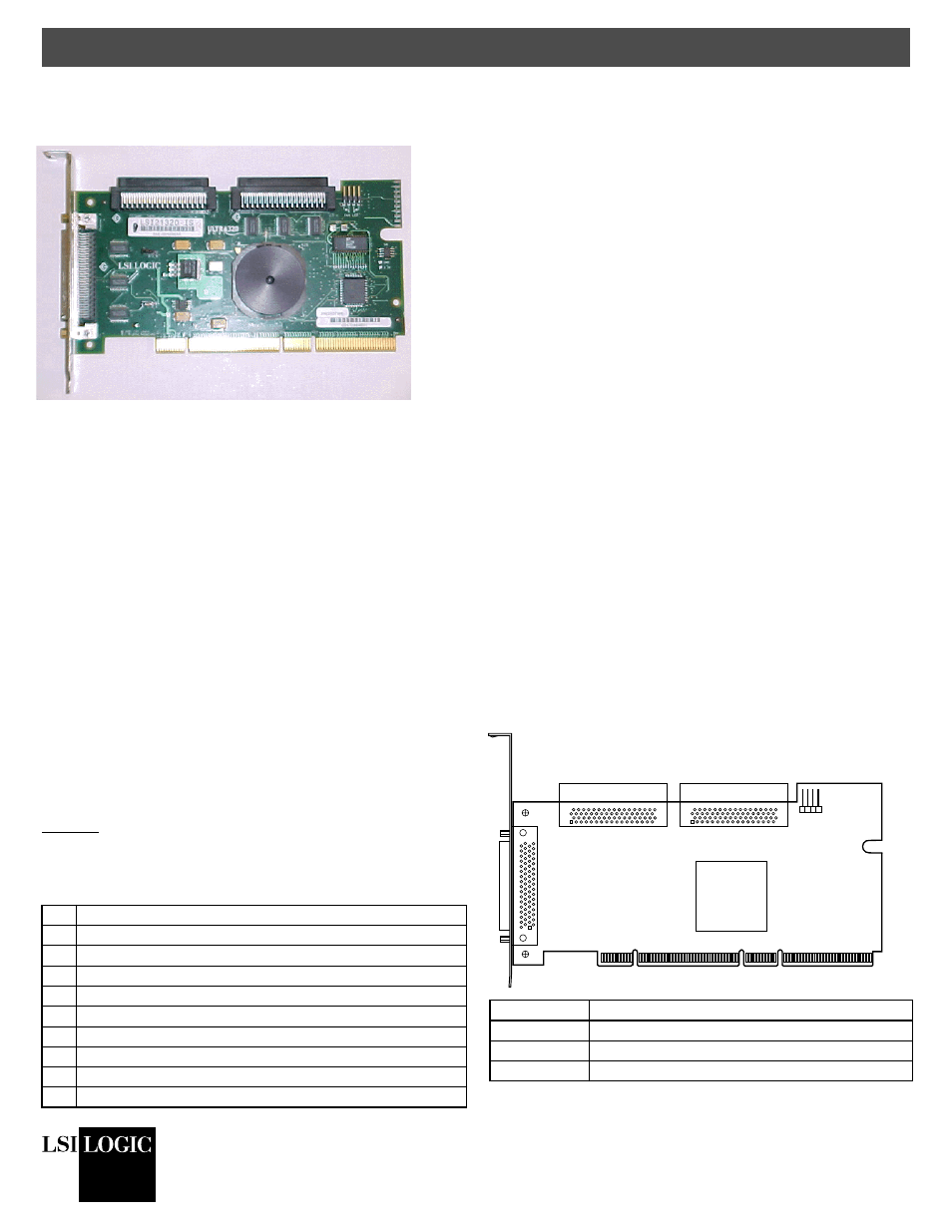
Figure 1
and the following table provide the location and
definition of the connectors on the LSI21320-R.
Figure 1 LSI21320-R Host Bus Adapter Board Drawing
Step Action
1
Unpack the LSI21320-R.
2
Turn off the computer, remove the power cord, and remove the cover.
3
Install the LSI21320-R in a PCI or PCI-X slot.
4
Connect the SCSI devices to the LSI21320-R.
5
Set the target IDs for the SCSI devices.
6
Set the SCSI termination.
7
Replace the computer cover and turn the power on.
8
Run the LSI Logic BIOS Configuration Utility.
9
Install the operating system device driver.
Connector
Definition
J1
PCI/PCI-X Connector
J2
External SCSI Channel A Connector
J3
Internal SCSI Channel B Connector
J1 - PCI/PCI-X
LSI53C1030
J2
Channel A
Ultra320 SCSI LVD/SE
J3
Channel B
Ultra320 SCSI LVD/SE
J6 for
Channels
A and B
J4
Channel A
Ultra320 SCSI LVD/SE