Avago Technologies LSI53C810AE User Manual
Page 3
3
Chapter 3, PCI Functional Description
Configuration Registers
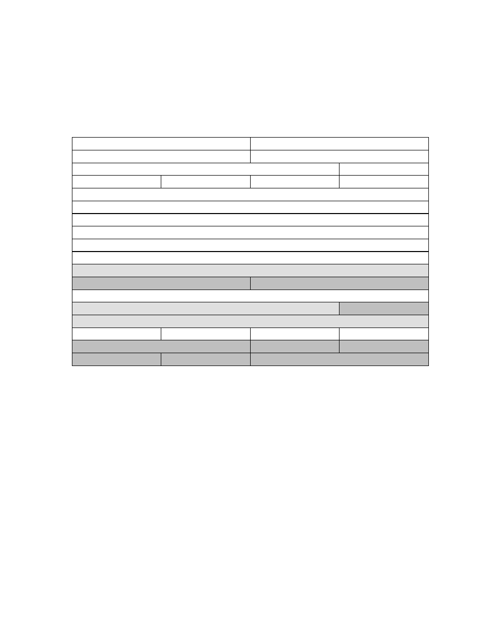
Figure 3-1: PCI Configuration Register Map
31
16
15
0
Device ID
Vendor ID = 1000h
00h
Status
Command
04h
Class Code
Rev ID
08h
Not Supported
Header Type
Latency Timer
Cache Line Size
0Ch
Base Address Zero (I/O), SCSI Operating Registers
10h
Base Address One (Memory), SCSI Operating Registers
14h
Base Address Two (Memory) SCRIPTS RAM
18h
Not Supported
1Ch
Not Supported
20h
Not Supported
24h
Reserved
28h
Subsystem ID
Subsystem Vendor ID
2Ch
Expansion ROM Base Address
30h
Reserved
Capabilities Pointer
34h
Reserved
38h
Max_Lat
Min_Gnt
Interrupt Pin
Interrupt Line
3Ch
Power Management Capabilities
Next Item Pointer
Capability ID
40h
Data
Bridge Support Ext
Pwr. Mgmt. Control/Status Register
44h
Note: Shaded areas are reserved or represent the SYM53C810AE capabilities.