Schematics – Avago Technologies ACPL-336J-000E User Manual
Page 3
Advertising
3
Schematics
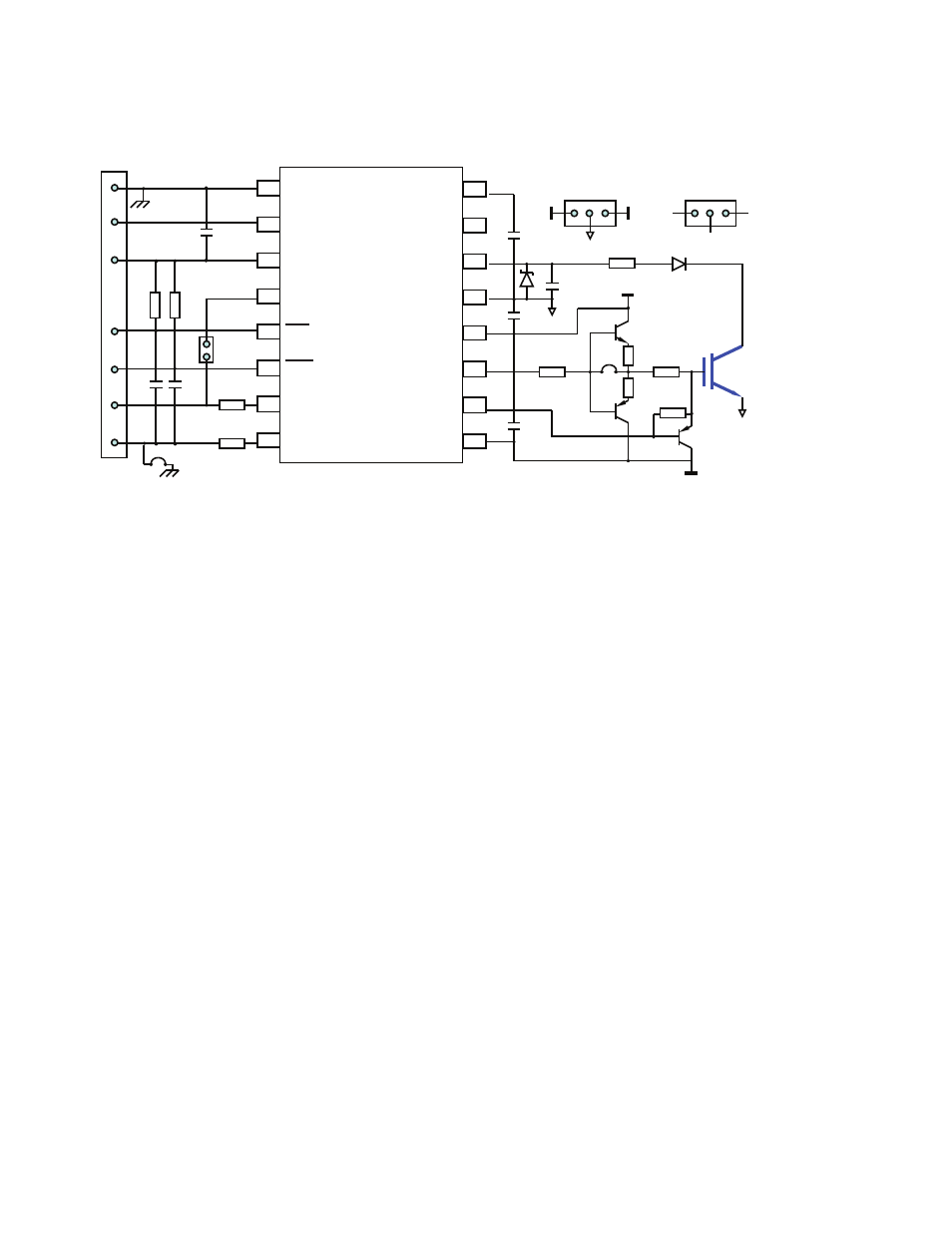
Figure 3 shows the schematics of the evaluation board.
Figure 3. Schematics of the ACPL-337J evaluation board
100pF
1
µF
T
A
1
µF
T
A
1
µF
T
A
2W
0R
V
CC2
1k
SBD
47
10
2W
nm
nm
1 kV
nm
nm
V EE2
V
CC2
V
EE2
CON3
G
E
CON4
C
G
C
E
nm
CON1
R1
R3
C1
C2
R4
Q1a
Q2
2STN2540
Q3
(TO247)
D1
C7 +
C4 +
C5 +
C6
R5
R6
R7
R8
J1
R2
nm : Not Mounted
CON2
10k
330pF
10k
330pF
150
150
BYV26E
PBSS4041SPN
BAT42W
Gnd
V E
V
E
V
E
J2
Gnd
1
µF
T
A
C3 +
Q1b
nm
nm
R9
R10
PBSS4041SPN
7,8
2
1
3
4
5,6
4,2
3
1
1
2
3
4
5
6
7
8
16
15
14
13
12
11
10
9
V
EE2
V
LED
V
E
V
CLAMP
V
OUT
DESAT
V
EE2
EE1
ANODE
UVLO
IN+
FAULT
CC1
LEDDRV
CATHODE
V
CC2
V
V
V
V
Advertising
This manual is related to the following products: