Using the board, Output measurement – Avago Technologies ACPL-339J-000E User Manual
Page 7
7
Using the Board
It is easy to prepare the evaluation board for use. Only minor preparations (just by soldering cables for DC supplies,
proper cables for HVDC+/HVDC
–
high voltage bus, and load connections) are required. The evaluation board has a
default setup (as shown in Table 2) when it is shipped to the customer. The customer is free to select different settings
for J1, S1 and S2 for his different needs.
Table 2
Recommended PWM frequency V
cc1
V
cc2
w.r.t. Vee
J1
S1
S2
Default Setup
1 kHz to 50 kHz (0 ~ 5 V)
+5Vdc
21.6 V ~ 30 V
Shorted
Shorted
Shorted
J1 is provided to let customer to adjust the DESAT fault detection voltage to 7 V by replacing it with another BYM26E.
S1 jumper is shorted to ground the IN1-. This can be open if differential signal is used across IN1+ & IN1– to drive the LED.
S2 jumper can be shorted when IGBT/Power MOSFET are not connected to Q5 (or Q6) to stop the DESAT fault from occurring. It
has to be open, however, when IGBT/Power MOSFET are connected to activate the DESAT fault protection.
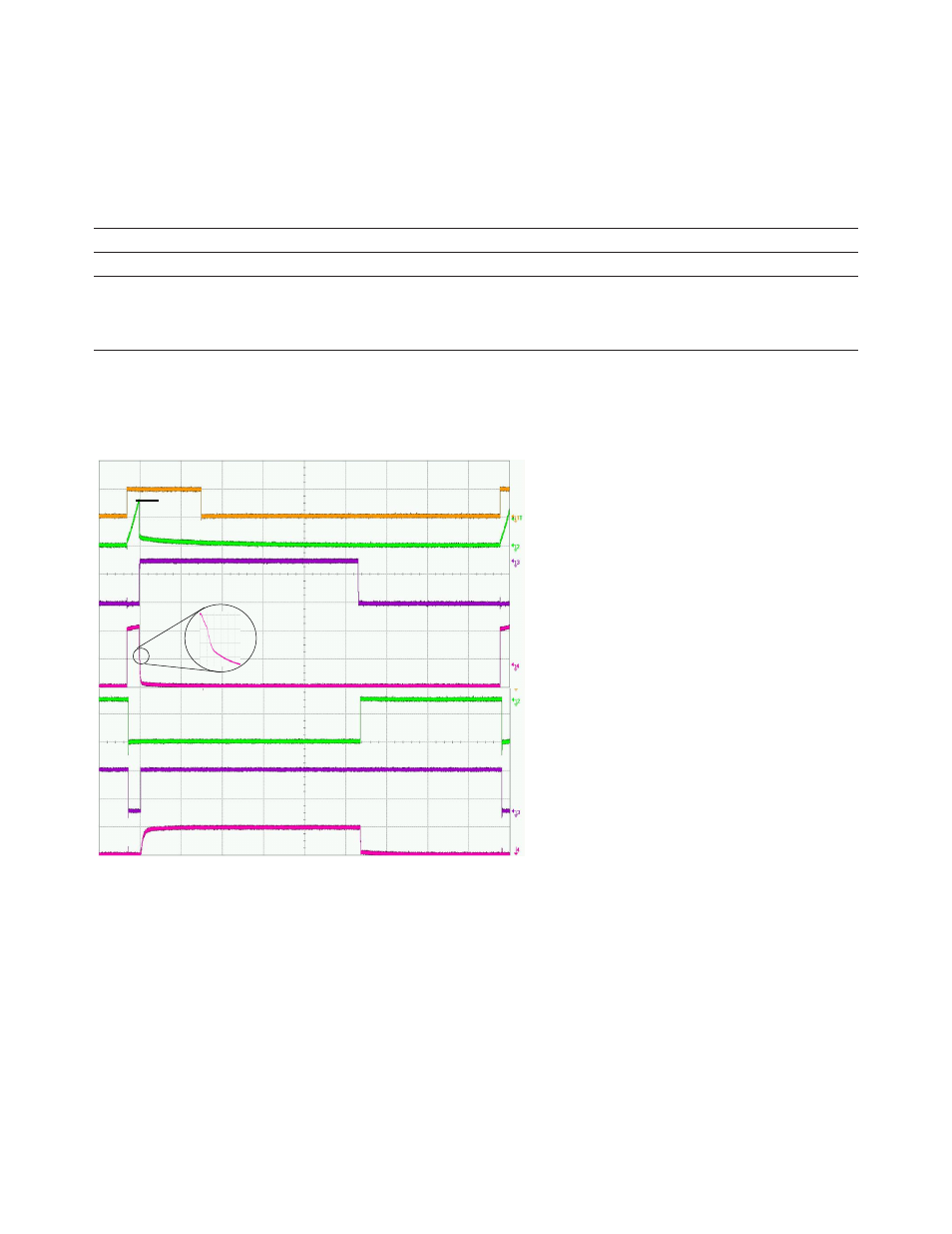
Output Measurement
Figure 5 and Figure 6 show a sample of Input LED and various output waveforms that have been captured. The soft
shutdown waveform are shown clearly in V
gIGBT
waveform.
Figure 5. Input LED (t
ON
< t
MUTE
) and various output voltage waveforms
LED ON
Soft
Shutdown
I
F
V
DESAT
8 V
LED OFF
V
GMOS
V
G(IGBT)
V
OUTN
V
OUTP
FAULT
Ext NMOS OFF
Ext NMOS ON
Ext PMOS OFF
Ext PMOS ON