Video operations – Roland VR-6HD Direct Streaming AV Mixer User Manual
Page 23
23
Video Operations
Input scan
1 .
Select “INPUT SCAN” for the operation mode. (p. 22)
The setup screen changes accordingly.
2 .
Use the [VALUE] knob to select a parameter shown below,
and press the [VALUE] knob.
Parameter
Explanation
SCAN SEQUENCE
Specifies the order in which video
signals are shown.
NORMAL:
Switches in the order of INPUT 1
Ó
6.
REVERSE:
Switches in the order of INPUT 6
Ó
1.
RANDOM:
Switches randomly.
SCAN TRANSITION TIME
Specifies the video transition time.
SCAN TARGET
Sets the video to which auto switching
is applied.
VIDEO INPUT:
Final output video and preview video
PinP & KEY 1–2:
PinP & KEY layer (inset screen) video
DSK:
DSK layer (inset screen) video
INPUT 1–6 TIME
Specifies the time that the video is
shown. Turn this “OFF” to skip.
* For details on the parameter, refer to “10: AUTO SWITCHING” (p. 130).
3 .
Use the [VALUE] knob to edit the value of the setting, and
press the [VALUE] knob.
4 .
Press the [MENU] button to close the screen.
Scene memory scan
1 .
Select “SCENE MEMORY SCAN” for the operation mode.
The setup screen changes accordingly.
2 .
Use the [VALUE] knob to select a parameter shown below,
and press the [VALUE] knob.
Parameter
Explanation
SCAN SEQUENCE
Specifies the order in which scene memories
are switched.
NORMAL:
Switches in the order of scene memory 1
Ó
32.
REVERSE:
Switches in the order of scene memory 32
Ó
1.
RANDOM:
Switches randomly.
MEMORY 1–32
TIME
Specifies the time it takes to switch to the next
scene memory. Turn this “OFF” to skip.
* For details on the parameter, refer to “10: AUTO SWITCHING” (p. 130).
3 .
Use the [VALUE] knob to edit the value of the setting, and
press the [VALUE] knob.
4 .
Press the [MENU] button to close the screen.
Beat sync
1 .
Select “BEAT SYNC” for the operation mode. (p. 22)
The setup screen changes accordingly.
2 .
Use the [VALUE] knob to select a parameter shown below,
and press the [VALUE] knob.
Parameter
Explanation
SYNC SOURCE
Sets the input audio that’s synchronized with
the video.
SCAN SEQUENCE
Specifies the order in which video signals are
shown.
NORMAL:
Switches in the order of INPUT 1
Ó
6.
REVERSE:
Switches in the order of INPUT 6
Ó
1.
RANDOM:
Switches randomly.
SCAN TRANSITION
TIME
Specifies the video transition time.
SCAN CYCLE
Sets the beat number on which the video
switches to the next one.
SCAN TARGET
Sets the video to which auto switching is
applied.
VIDEO INPUT:
Final output video and preview video
PinP & KEY 1–2:
PinP & KEY layer (inset screen) video
DSK:
DSK layer (inset screen) video
* For details on the parameter, refer to “10: AUTO SWITCHING” (p. 130).
3 .
Use the [VALUE] knob to edit the value of the setting, and
press the [VALUE] knob.
4 .
Press the [MENU] button to close the screen.
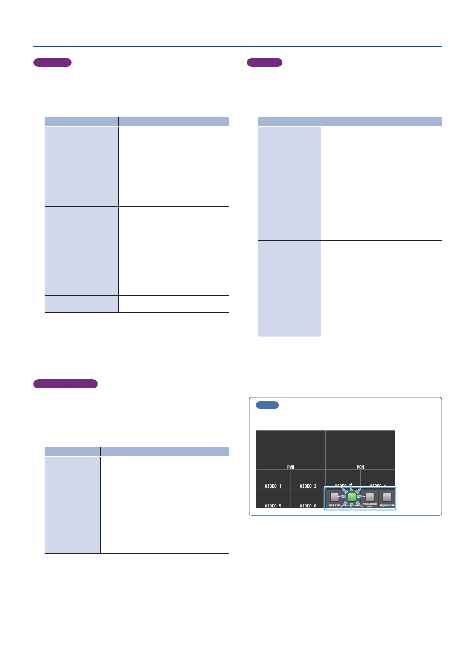
MEMO
When an auto-switching function is assigned to a USER button on the
dashboard, the USER button blinks in time with the current BPM.