Energizer ENF-600C Digital TTL Flash for Cameras User Manual
Energizer Storage
97169
MANUAL FLASH CONTROL
This flash unit provides manual flash mode, allowing you to control the light output at your desired level. 6
power settings 1/1, 1/2, 1/4, 1/8, 1/16 and 1/32 are available. To use the manual mode, please follow the
instruction below:
(1) Tap the MODE button until the “M” indicator shows up on the LCD.
(2) Then press the “ ” or “ ” selector button to set your desired flash output level. The setting will then be
automatically saved to the internal memory.
The LCD automatically shows a flash-to-subject distance required for correct exposure.
SLAVE MODE
Optical slave sensor is built into this flash unit, so it can be used as a slave flash. It can instantly synchronize
with external trigger (S0 Mode).
The amount of light output at slave mode can be set in manaul mode. The following guides you through how
to use the slave function of this flash:
(1) Follow the instructions in the section ‘MANUAL FLASH MODE’ to set the output power of the flash.
(2) Tap the MODE button till the indicator ‘S’ (Slave) and ‘0’ shows up on the LCD.
FLASH SYNCHRONIZATION
Synchronization time refers to the shutter speeds that enable flash photography. Each camera model
features a “shortest” synchronization called x-synchronization. Please refer to the user guide of your camera
for details. Shutter speeds slower than the x-synchronization should never be used in order to avoid incorrect
exposures.
When the camera is in program mode (P) or aperture-priority mode (A), and an external flash unit is used, the
x-synchronization of the camera will automatically be adjusted to assure proper exposure. The sync speed
depends on the camera models and usually ranges between 1/30sec to 1/250sec.
When a flash shot has been taken, "OK" indicator lights up shortly to confirm correct exposure.
SLOW SYNCHRONIZATION
The Slow Synchronization function is available with cameras that support this feature. The flash is controlled
at a slow shutter speed to obtain the correct exposure for both the main subject and background in low-light
situations or at night.
This function can only be set on the camera, not on the flash unit. For more information, refer to your camera
manual.
As slow shutter speeds are normally used for slow sync, a tripod is recommended to prevent camera shake.
FRONT AND REAR-CURTAIN SYNCHRONIZATION
Some cameras offer the option of rear curtain synchronization (Rear mode) triggering the flash unit at the end
of the exposure time. Rear curtain synchronization is particularly advantageous when using slow shutter
speeds (slower than 1/30 sec.) or when shooting moving objects that have their own source of light. Rear
curtain synchronization gives a more realistic impression of movement because the light streaks behind the
light source instead of building up in front of it, as is the case when the flash is synchronized with the front
shutter curtain. Depending on its operation mode, the camera uses shutter speeds slower than its sync
speed.
For Type P flash: You could select the synchronization mode as either front curtain ( ) or rear curtain
( ) at the back of the flash. The flash will fire according to the mode selected to match with the camera
shutter.
For Type C, N, OP, SA flash: The camera controls front or rear-curtain synchronization, therefore no setting is
required to be done on the flash.
RED EYE REDUCTION (FOR TYPE N, OP, P)
To prevent the center of your subject’s eyes from appearing red in color pictures, the flash unit fires
pre-flashes at reduced output just before the picture is taken.
The Red Eye Reduction function is available with cameras that have red-eye reduction control. This function
can only be set on the camera, not on the flash unit. For more information, refer to your camera manual.
WIRELESS TTL FUNCTION
This flash is equipped with advanced wireless TTL flash function. It can synchronize with a master flash or
the camera’s built-in flash through TTL. You can use your flash away from the camera but still enjoy the
convenience of TTL photography.
Before going thru the operation, you should be familiar firstly with the following nomenclature used in wireless
flash photography:
Master flash
The camera’s built-in flash, a flash unit mounted on the camera, or the one directly connected to the camera
via a extension cord is called the Master Flash. Only one master flash is allowed in a wireless multiple flash
photography setting. It controls how the Remote Flashes are operated in Wireless TTL mode.
Remote flash
The flash unit placed off the camera is called “Remote Flash” (Canon calls it “Slave’’). There is no limitation
on the numbers of remote flash to set in one time.
Groups
In wireless photography, you can assign remote flash units into any one of the three groups (A, B, or C) and
set the mode and output level compensation values for each remote flash unit.
Channels
The master and remote flash units exchange data through channels. In this flash, three channels 1, 2 and 3
are available. You pick the channel you prefer for communication between the master and remote flash units.
If another photographer uses the same type of wireless photography setup nearby, your remote flash units
may accidentally fire in sync with that photographer’s master flash unit. Therefore, you should choose the
channel carefully in order to avoid such situation.
How to use
This flash can be used as a remote flash in wireless multiple flash photography. To do this, please follow the
instructions below:
(1) Tap the MODE button until the indicator STTL (Wireless TTL mode) shows up on the LCD.
(2) Press the “ ” or “ ” selector button to set your desired wireless TTL channel and group.
For Type C, N, and O flash: Each tap on the “ ” button changes the wireless channel and group setting in
the following sequence: 1A
→
1B
→
1C
→
2A
→
2B
→
2C
→
3A
→
3B
→
3C. The “ ” button changes the
setting in reverse steps.
For Type P and SA flash: Pentax and Sony do not support grouping of flashes in a channel. Therefore, Each
tap on the “ ” button changes the wireless channel setting in the following sequence: 1
→
2
→
3. The “ ”
button changes the setting in reverse steps.
You will see a red light blinking continuously from the front red Iens when the wireless TTL function is
activated.
If you are using multiple flashes in your wireless photography setting, you should avoid setting more than 3
flash units in one group in order to avoid interference between flashes.
(3) Set your preferred flash coverage angle by pressing the ZOOM button.
(4) Place your flash unit in consideration of the followings:
a. The flash should not shoot its light directly into the camera lens.
b. Make sure that the wireless sensor is facing the master flash and the path is not blocked.
c. In the daylight synchronization, the wireless sensor may possibly be saturated by sunlight and its sensitivity
be extremely reduced. It is recommended that you make a shade to cover the sensor in this situation.
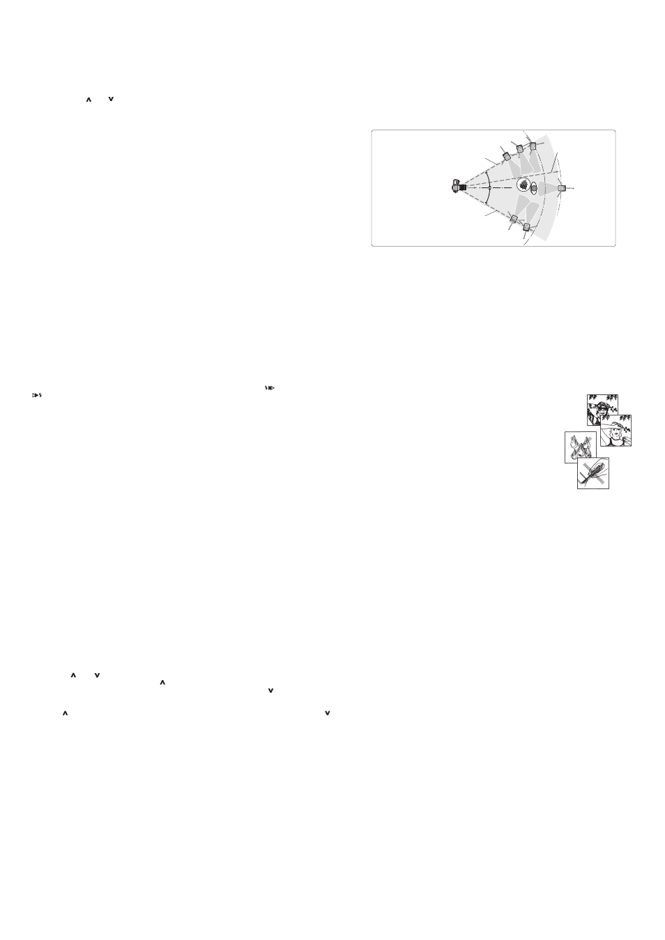
Flash setup scenerio in wireless photography
Use the camera’s built-in flash or attach a flash onto the hot shoe of the camera as your master flash.
Set up the remote flash/flashes at any desirable location within the effective shooting range.
The effective shooting distance between the master and remote flash units is approx. 10m (33 ft.) or less
in the front position, and approx. 5 to 7m (16 to 23 ft.) at both sides. These ranges may vary depending
on the ambient light.
Make sure the channel and the group setting in each remote flash is set correctly. Remote flashes of the
same group should be placed together.
SAFETY INSTRUCTION
• Do not fire flashes from a short distance directly into the eyes of persons or animals. This can cause
damage to the retina and may even lead to blindness.
• Use only the power sources specified in the operation instructions.
• Never attempt to open or short-circuit batteries.
• Never expose dry or rechargeable batteries to excessive temperature such as intensive sunlight or fire.
• Always switches off the flashgun before changing the batteries.
• Do not attempt to open the flashgun because the electronic circuit contains high voltage. There are no
components inside the flashgun, which can be repaired by the user.
• If in case of the flashgun is so badly damaged that internal components are exposed, the flashgun may not
be used until it has been repaired. Remove the batteries to prevent inadvertent use.
• Never try to repair the flashgun by yourself. If there are any problems, please contact the customer service.
WARNING
This flash unit may halt and could not function when the battery power is not sufficient or when user operates
this unit in an inappropriate way
Please switch off the flash unit by its main switch when it is not working correctly. Wait for a few seconds and
replace the battery if necessary before switching it on again. The flash unit should work again as normal
afterward.
>=30°
>=30°
Be sure to direct the wireless sensor window of
the remote flash unit toward the master flash.
Group B
Less than approx.
10m (33 ft.)
Approx. 5 to 7 m
(16 to 23 ft.)
Group C
Group A
Master flash
Approx. 5 to 7 m
(16 to 23 ft.)