Sennheiser SI 1015-8000 Dual System Package User Manual
Page 7
13
12
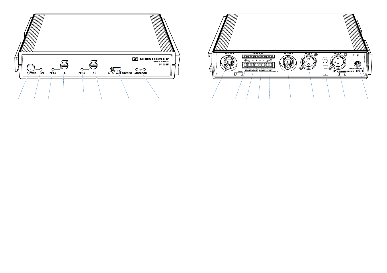
Connections and operating elements of the SI 1015 (front panel)
ON/OFF switch
LED power indicator
Overmodulation indicator channel A
Level control channel A
Overmodulation indicator channel B
Level control channel B
Channel selector switch:
channel A
channel B
channel A/B, 2 x mono
channel A and B, stereo
IR transmitting diodes (for direct monitoring via an IR receiver)
Connections and operating elements of the SI 1015 (back panel)
RF output socket 1 for connecting a radiator
Barrier strip RF contacts 1 for connecting a radiator
(alternative connection to
, wired in parallel)
Barrier strip DC outputs for radiator 1
Barrier strip DC outputs for radiator 2
Barrier strip RF contacts 2 for connecting a radiator
(alternative connection to
, wired in parallel)
RF output socket 2 for connecting a radiator (same signal as
)
AF input B
Cable grip
AF input A
Input socket for plug-in mains unit – power supply, 25 - 35 V DC via NT 1015
plug-in mains unit or via a different DC source.