BOSS FS-6 - Dual Latch and Momentary Footswitch Pedal User Manual
Owner’s manual, Warning, Caution
Thank you, and congratulations on your choice of BOSS FS-6 Dual Foot Switch. Before using this unit, carefully read the sections entitled:
“USING THE UNIT SAFELY”
and
“IMPORTANT NOTES.”
These sections provide important information concerning the proper operation of the unit. Additionally, in order to feel assured that you have gained a good grasp of every feature provided by
your new unit, this manual should be read in its entirety. The manual should be saved and kept on hand as a convenient reference.
Features
5
This unit combines the functions of the FS-5L (latch type) and FS-5U (momentary type) foot switches. Both of the unit’s foot switches
may be set to function as either a latch or momentary type switch.
5
You can connect to gear equipped with TRS 1/4” phone jacks using a connection cable with stereo 1/4” phone plugs at both ends.
5
The FS-6 can be connected to another FS-6, a FS-5U/5L, or an AB-2.
Use the FS-6 with BOSS or Roland devices compatible
with the FS-5L or FS-5U.
* No assurances can be given with respect to the proper
functioning of this unit if it is connected with devices or jacks
other than those specified.
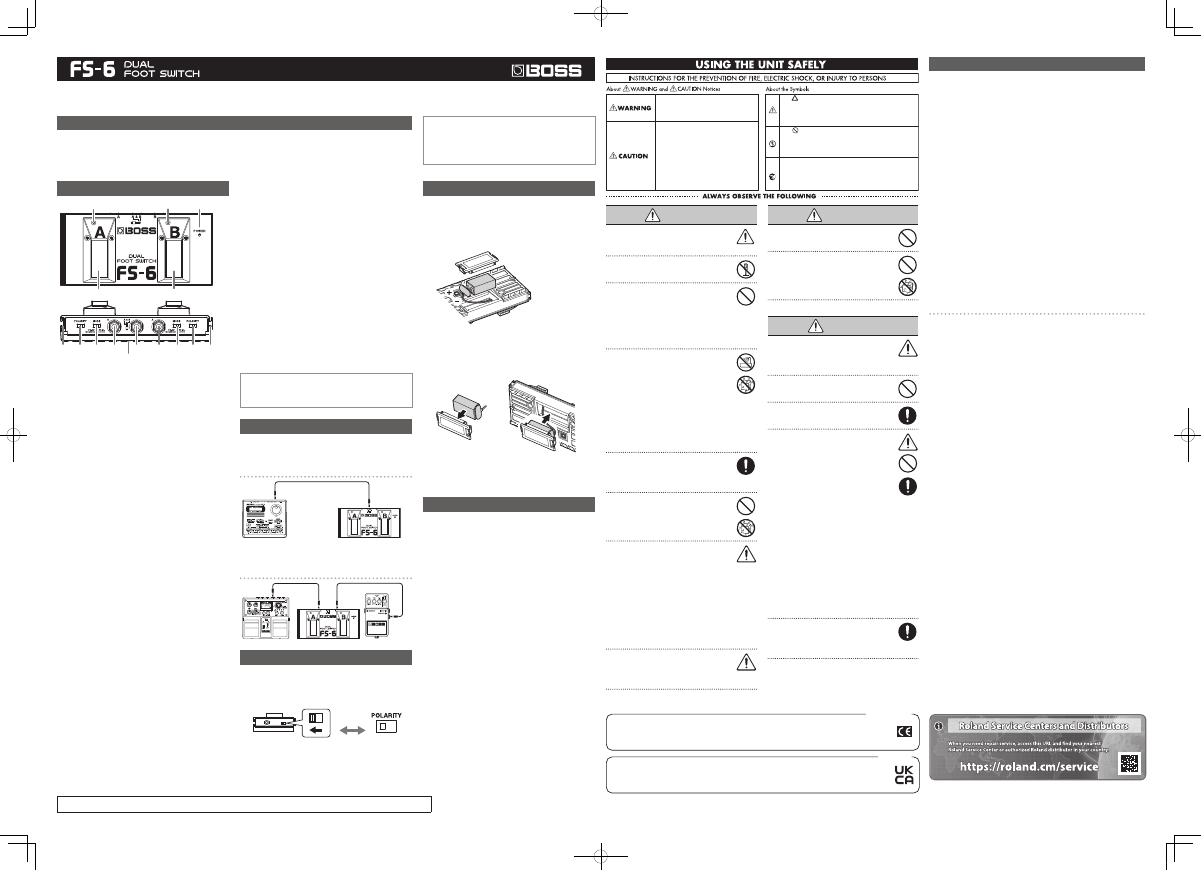
Panel Description
1
2
3
4
12
8
10
5
7
13
6
11
9
14
14
1.
Pedal Switch A
Use this as a switch for the device connected to Jack A or
Jack A & B. Refer to “Connections.”
2.
Pedal Switch B
Use this as a switch for the device connected to Jack B or
Jack A & B. Refer to “Connections.”
3.
Pedal Switch A Indicator
When pedal switch A is set to the latch type function,
this indicator alternately lights or goes out each time the
pedal switch is pressed. When pedal switch A is set to the
momentary type function, this indicator lights only while
the pedal switch is held down.
4.
Pedal Switch B Indicator
When pedal switch B is set to the latch type function,
this indicator alternately lights or goes out each time the
pedal switch is pressed. When pedal switch B is set to the
momentary type function, this indicator lights only while
the pedal switch is held down.
5.
Jack A
Connect the device being controlled with pedal switch
A here. Use a connection cable with 1/4” phone plugs at
both ends.
6.
Jack B
Connect the device being controlled with pedal switch
B here. Use a connection cable with 1/4” phone plugs at
both ends.
7.
Jack A & B
Connect devices equipped with TRS 1/4” phone jacks
here. Use a connection cable with stereo 1/4” phone
plugs at both ends.
* Jacks A, B, and A & B also function as power switches. The power
is switched on when a plug is inserted in any of these jacks, and
switched off when no plug is connected. Unplug any cable from
these jacks whenever you are not using the unit.
8.
POLARITY Switch A
This switches the polarity of pedal switch A.
After referring to the owner’s manual for the device you
are connecting, switch this to the appropriate setting.
9.
POLARITY Switch B
This switches the polarity of pedal switch B.
After referring to the owner’s manual for the device you
are connecting, switch this to the appropriate setting.
10.
MODE Switch A
This sets the function for pedal switch A to LATCH or
MOMENTARY.
11.
MODE Switch B
This sets the function for pedal switch B to LATCH or
MOMENTARY.
LATCH:
Alternately switches on or off each time the pedal switch
is pressed.
MOMENTARY:
Switches on (off) while the pedal switch is held down,
and off (on) when the switch is released.
12.
POWER Indicator
This lights when the power is on (when a plug is
connected to a jack).
* If this indicator goes dim or no longer lights while the power
is on, the battery is near exhaustion and should be replaced
immediately.
13.
Battery Cover
Open this cover to replace the battery. For instructions on
replacing the battery, refer to “Changing the Battery.”
14.
FS Joint Panel
The FS-6 can be connected to another FS-6, a FS-5U/5L,
or an AB-2.
Before Using
Connect the battery supplied to the snap cord with
correct polarity.
Connections
* To prevent malfunction and/or damage to speakers or other
devices, always turn down the volume, and turn off the power on
all devices before making any connections.
Connecting to Jack A & B
Connection Cable
(stereo 1/4” phone plugs at both ends)
* When connecting to Jack A & B, do not plug any device into Jack A
or Jack B. This may result in damage and/or malfunction.
Connecting to Jack A or B
Setting the POLARITY Switch
When matching the FS-6’s polarity setting with the polarity
setting for the FS-5U or FS-5L given in the owner’s manual for
the device being connected, set as described below.
* According to these settings, the setting switches to OPEN when
the switch is on and CLOSE when the switch is off.
FS-5L / FS-5U
FS-6
Changing the Battery
When the POWER indicator goes dim or no longer lights
while the power is on, it means that the battery is nearly
dead and must be replaced.
* When turning the unit upside-down, handle with care to avoid
dropping it, or allowing it to fall or tip over.
1.
Open the battery cover.
When changing the battery,
be careful not to touch the
circuit board inside the unit.
*
2.
Remove the old battery from the battery housing, and
remove the snap cord connected to it.
3.
Connect the snap cord to the new battery.
* Be sure to carefully observe the battery’s polarity (+ versus -).
4.
Place the battery inside the housing.
5.
While holding the assembly carefully, so the battery
cover doesn’t get separated from the battery, close the
battery cover.
* Press the cover until you hear it click into place.
Troubleshooting
Power not turning on (POWER indicator not lighting)
p
Is the cable fully plugged into the jack?
"
The power switches when a cable is plugged into one of the
jacks. Make sure the cable is plugged in firmly and securely.
p
Is the battery dead?
"
Replace the battery with a new one as described in
“Changing the Battery.”
p
Are you using a connection cable with stereo 1/4”phone
plugs at both ends to connect to Jack A or Jack B?
"
Use a connection cable with mono 1/4” phone plugs at
both ends.
Connected device not operating properly
p
Have you connected to the appropriate jack on the device?
"
Check the type of jack used on the device being connected.
p
Is the POWER indicator dimmed or off?
"
The battery may be dead. Replace the battery with a new
one as described in “Changing the Battery.”
p
Is the setting of the POLARITY switch correct?
"
Set the polarity in accordance with the specifications for
the connected device.
p
Is the MODE switch setting correct?
"
Set the MODE in accordance with the specifications for the
connected device.
Pedal switch indicator not lighting
p
Is the switch off?
"
Depress the pedal switch.
p
Is the POLARITY switch set firmly in the correct position?
"
Make sure the POLARITY switch is set securely in the
correct position.
Indicator dimmed/off
"
The battery may be dead. Replace the battery with a new
one as described in “Changing the Battery.”
This unit is a dedicated foot control device. Do not use it for any purpose other than those described in the owner’s manual.
Used for instructions intended to alert the
user to the risk of injury or material
damage should the unit be used
improperly.
* Material damage refers to damage or
other adverse effects caused with
respect to the home and all its
furnishings, as well to domestic animals
or pets.
Used for instructions intended to alert the
user to the risk of death or severe injury
should the unit be used improperly.
The
●
symbol alerts the user to things that must be
carried out. The specific thing that must be done is
indicated by the design contained within the circle. In the
case of the symbol at left, it means that the power-cord
plug must be unplugged from the outlet.
The symbol alerts the user to important instructions or
warnings. The specific meaning of the symbol is
determined by the design contained within the triangle. In
the case of the symbol at left, it is used for general
cautions, warnings, or alerts to danger.
The symbol alerts the user to items that must never be
carried out (are forbidden). The specific thing that must
not be done is indicated by the design contained within
the circle. In the case of the symbol at left, it means that
the unit must never be disassembled.
WARNING
Before using this unit, make sure to read
the instructions below, and the Owner's
Manual.
Do not open (or modify in any way) the
unit.
Do not attempt to repair the unit, or
replace parts within it (except when this
manual provides specific instructions
directing you to do so). Refer all servicing
to your retailer, the nearest Roland Service
Center, or an authorized Roland distributor,
as listed on the "Information."
Never use or store the unit in places that are:
•
Subject to temperature extremes (e.g.,
direct sunlight in an enclosed vehicle,
near a heating duct, on top of heat-
generating equipment); or are
•
Damp (e.g., baths, washrooms, on wet floors); or are
•
Humid; or are
•
Exposed to rain; or are
•
Dusty; or are
•
Subject to high levels of vibration.
Make sure you always have the unit placed
so it is level and sure to remain stable.
Never place it on stands that could
wobble, or on inclined surfaces.
Do not allow any objects (e.g., flammable
material, coins, pins); or liquids of any kind
(water, soft drinks, etc.) to penetrate the
unit.
Immediately turn the power off, and request
servicing by your retailer, the nearest Roland
Service Center, or an authorized Roland
distributor, as listed on the "Information" when:
•
If smoke or unusual odor occurs
•
Objects have fallen into, or liquid has been spilled
onto the unit; or
•
The unit has been exposed to rain (or otherwise
has become wet); or
•
The unit does not appear to operate normally or
exhibits a marked change in performance.
In households with small children, an
adult should provide supervision until the
child is capable of following all the rules
essential for the safe operation of the unit.
WARNING
Protect the unit from strong impact.
(Do not drop it!)
Batteries must never be recharged,
heated, taken apart, or thrown into fire or
water.
CAUTION
Try to prevent cords and cables from
becoming entangled. Also, all cords and
cables should be placed so they are out of
the reach of children.
Never climb on top of, nor place heavy
objects on the unit.
Disconnect all cords coming from external
devices before moving the unit.
If used improperly, batteries may explode
or leak and cause damage or injury. In the
interest of safety, please read and observe
the following precautions.
•
Carefully follow the installation
instructions for batteries, and make sure
you observe the correct polarity.
•
Remove the batteries whenever the unit is
to remain unused for an extended period of time.
•
If a battery has leaked, use a soft piece of cloth or
paper towel to wipe all remnants of the discharge
from the battery compartment. Then install new
batteries. To avoid inflammation of the skin, make
sure that none of the battery discharge gets onto
your hands or skin. Exercise the utmost caution
so that none of the discharge gets near your eyes.
Immediately rinse the affected area with running
water if any of the discharge has entered the eyes.
•
Never keep batteries together with metallic objects
such as ballpoint pens, necklaces, hairpins, etc.
Used batteries must be disposed of in
compliance with whatever regulations for
their safe disposal that may be observed in
the region in which you live.
Roland Corporation
2036-1 Nakagawa, Hosoe-cho, Kita-ku, Hamamatsu, Shizuoka 431-1304, JAPAN
Roland Corporation
ENA 23 Zone 1 nr. 1620 Klaus-Michael Kuehnelaan 13, 2440 Geel, BELGIUM
Importer:
Manufacturer:
For EU Countries
Roland Corporation
2036-1 Nakagawa, Hosoe-cho, Kita-ku, Hamamatsu, Shizuoka 431-1304, JAPAN
Roland Europe Group Limited
Hive 2, 1530 Arlington Business Park, Theale, Reading, Berkshire. RG7 4SA United Kingdom
Importer:
Manufacturer:
For the U.K.
Specifications
Controls
Pedal Switch A, B / POLARITY Switch A, B / Mode Switch A, B
Connectors
Jack A, Jack B (1/4 inch phone type)
Jack A & B (TRS 1/4 inch phone type)
Power Supply
DC 9 V: Dry battery/9 V 6F22 (carbon), 6LR61 (alkaline)
* Expected battery life under continuous use:
Carbon: 70 hours, Alkaline: 100 hours
(A and B = ON, MODE = LATCH)
These figures will vary depending on the actual conditions of use.
Current Draw
8 mA (max.)
Dimensions
188 (W) x 91 (D) x 43 (H) mm
7-7/16 (W) x 3-5/8 (D) x 1-3/4 (H) inches
Weight
470 g / 1 lb 1 oz (including battery)
Accessories
Dry battery/9 V (6F22), Owner’s Manual
* In the interest of product improvement, the specifications and/or appearance of this
unit are subject to change without prior notice.
IMPORTANT NOTES
In addition to the items listed under “USING THE UNIT SAFELY”, please
read and observe the following:
Power Supply: Use of Batteries
5
Batteries should always be installed or replaced before connecting any other
devices. This way, you can prevent malfunction and/or damage to speakers or
other devices.
5
A battery was installed in the unit before it left the factory. The life of this battery
may be limited, however, since its primary purpose was to enable testing.
5
Before connecting this unit to other devices, turn off the power to all units. This
will help prevent malfunctions and/or damage to speakers or other devices.
Placement
5
Noise may be produced if wireless communications devices, such as cell phones,
are operated in the vicinity of this unit. Such noise could occur when receiving or
initiating a call, or while conversing. Should you experience such problems, you
should relocate such wireless devices so they are at a greater distance from this
unit, or switch them off.
5
Do not expose the unit to direct sunlight, place it near devices that radiate
heat, leave it inside an enclosed vehicle, or otherwise subject it to temperature
extremes. Excessive heat can deform or discolor the unit.
5
When moved from one location to another where the temperature and/or
humidity is very different, water droplets (condensation) may form inside the
unit. Damage or malfunction may result if you attempt to use the unit in this
condition. Therefore, before using the unit, you must allow it to stand for several
hours, until the condensation has completely evaporated.
Maintenance
5
For everyday cleaning wipe the unit with a soft, dry cloth or one that has been
slightly dampened with water. To remove stubborn dirt, use a cloth impregnated
with a mild, non-abrasive detergent. Afterwards, be sure to wipe the unit
thoroughly with a soft, dry cloth.
5
Never use benzine, thinners, alcohol or solvents of any kind, to avoid the
possibility of discoloration and/or deformation.
Additional Precautions
5
Use a reasonable amount of care when using the unit’s buttons, sliders, or other
controls; and when using its jacks and connectors. Rough handling can lead to
malfunctions.
5
When connecting / disconnecting all cables, grasp the connector itself-never pull
on the cable. This way you will avoid causing shorts, or damage to the cable’s
internal elements.
5
To avoid disturbing your neighbors, try to keep the unit’s volume at reasonable
levels (especially when it is late at night).
5
When you need to transport the unit, package it in the box (including padding)
that it came in, if possible. Otherwise, you will need to use equivalent packaging
materials.
© 2004 Roland Corporation
BOSS is a registered trademark of Roland Corporation in the United States
and/or other countries.
Owner’s Manual
Fs-6_eng.indd 1
2021/07/16 14:48:14
Document Outline
- 取扱説明書
- 主な特長
- 各部の名称と働き
- 接続のしかた
- ジャックA & B との接続
- ジャックA またはB との接続
- POLARITY スイッチの設定
- 電池交換のしかた
- 故障と思う前に
- 安全上のご注意
- 主な仕様
- 使用上のご注意
- Owner’s Manual