Futaba DLPH-1 Dual-Link Power Hub User Manual
Dlph-1, Instruction manual
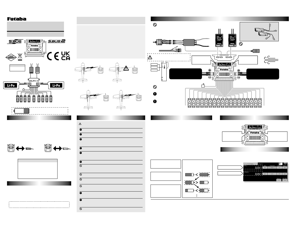
Install two receivers on the aircraft as shown in the wiring diagram on the
next page.
Link the two receivers using the dual receiver feature of the transmitter.
For systems without dual receiver capability, link each receiver in turn.
WARNING
If the connector is disconnected during flight, it becomes inoperable.
As with any electronic components, proper precautions are urged to pro-
long the life and increase the performance of the unit.
It will not work unless the two receivers are linked. After startup, even if
the link on one side is disconnected, the other side will continue to oper-
ate normally.
Use a dedicated battery to power the receiver / servo.
Large current flows through the Rx port of DLPH-1 and is damaged.
There is a risk of explosion, fire and damage.
Reference: Although it depends on the servo used and flight style, acro
flight with 15 HPS servos has been confirmed.
Do not fly until inspection is complete.
Check if the DLPH-1 switches.
Thank you for purchasing the DLPH-1. Before using your new DLPH-1, please
read this manual thoroughly and use the DLPH-1 properly and safely. After read-
ing this manual, store it in a safe place.
Use :
Two receivers and two batteries communication
switching device
Size :
62.8Ч62.4Ч18.1 mm
(
2.47Ч2.46Ч0.71
in)
Weight :
50 g (1.76 oz)
FET rated :
Always 60 A / 2 pcs
Operating voltage :
DC6.4 V to 13.0 V
Accessories:
Switch / Receiver connection cord x 2
/ Mini screwdriver/ Flange damper / Eyelet / Wood screw
7R6%866%86SRUW
:KHQXVLQJ(6&
9DULRXVWHOHPHWU\VHQVRUV6%86J\URHWF
6ZLWFK
(6&
5HFHLYHUق6HUYRك%DWWHU\
ٴ/L)HFHOOV岜9
ٴ/L3RFHOOV岜9
ٴق/L3RFHOOV岜9ك
ٴ/L)HFHOOV岜9
ٴ/L3RFHOOV岜9
ٴق/L3RFHOOV岜9ك
5HFHLYHUق6HUYRك%DWWHU\
6%86
&+
&+
&+
&+
&+
&+
&+
&+
&+
&+
&+
&+
&+
&+
&+
&+
&+
&+
6%86
FUTABA CORPORATION
Hobby Radio Control Business Center Sales & Marketing Department
1080 Yabutsuka, Chosei-mura, Chosei-gun, Chiba-ken, 299-4395, Japan
TEL: +81-475-32-6051, FAX: +81-475-32-2915
©FUTABA CORPORATION 2021, 10 (1)
Use a dedicated battery to power the receiver / servo.
This receiver employs an electronic switching (current is controlled by an FET circuit)
system. When the exclusive switch is set to ON or is pulled, the power is turned on.
Switches other than the exclusive switch cannot be used. In addition, since a very
VPDOOFXUUHQWÀRZVHYHQZKHQWKHSRZHULVR൵DOZD\VGLVFRQQHFWWKHEDWWHU\IURPWKH
connector when the receiver is not in use.
One or 2 batteries can be connected. When 2 batteries are connected, the battery with
the highest voltage is used. When only one battery is connected, always insulate the
unused connector. The battery can be connected to either side.
8VHEDWWHULHVZLWKVX൶FLHQWFDSDFLW\IRUWKHVSHFL¿FDWLRQVDQGQXPEHURIVHUYRPRWRUV
to be used.
7KHEDWWHU\/('RQWKHVLGHEHLQJXVHGOLJKWVXS,WWXUQVR൵ZKHQHDFKEHFRPHV9RUOHVV
Two power supply batteries can be connected to the DLPH-1. Power is supplied
from the battery with the highest voltage. The operating time is the total time of the 2
batteries. For example, even if the voltage of one battery drops, power can be supplied
IURP WKH RWKHU EDWWHU\ (YHQ RQH EDWWHU\ FDQ EH XVHG EXW VDIHU ÀLJKW LV SRVVLEOH LI
batteries are used.
DLPH-1
Instruction Manual
The DLPH-1 is equipped with a telemetry sensor function. The receiver voltage displayed on the
transmitter home screen is only a constant value. The voltages of battery 1 and battery 2 should
be monitored by telemetry voltage.
DLPH-1 uses two continuous slots. Please note that the proper default start slot for this accessory
is number 6. When setup-changing or adding, it is the following numbers that are made to a start
slot.
1,2,3,4,5,6,8,9,10,11,12,13,14,16,17,18,19,20,21,22,24,25,26,27,28,29,30
By connecting the transmitter and SB2 port, it is possible to register to the transmitter and change
the start slot. In that case, it is necessary to connect the battery to DLPH-1 and supply power.
Information on how to change the slot assignment is included in the transmitter's manual.
ots Please note that the proper default start slot for this accessory
Mounting hole dimensions
)RUUHFHLYHUVWKDWFDQVHWWKHEDWWHU\)6VHWWKHEDWWHU\)6WR9
or less or OFF.
Also, make sure that the battery F / S of the two receivers have the same
settings.
6LQFHWKHRXWSXWYROWDJHIURP'/3+LV9LIWKHEDWWHU\)6LVVHWWR
9RUKLJKHUWKHEDWWHU\)6ZLOODOZD\RSHUDWH