Kramer 4X1VB Mechanical Video Switcher, 4x1, Composite (BNC), Mini Series User Manual
4x1v, 4x1vb quick start guide, Step 1: check what’s in the box, Step 3: connect inputs and outputs
4x1V,
4x1VB
Quick Start
P/N: 2 9 0 0 - 3 0 1 2 8 3 QS
Rev: 2
Scan for full manual
4x1V, 4x1VB Quick Start Guide
This guide helps you install and use your
4x1V, 4x1VB
for the first time.
Go to
o download the latest user manual and check if firmware
upgrades are available.
Step 1: Check
what’s in the box
4x1V
or
4x1VB
4:1 Video Switcher
1 Quick start guide
4 Rubber feet
1 User manual
Step 2: Mount 4x1V, 4x1VB
Install
4x1V, 4x1VB
using one of the following methods:
•
Attach the rubber feet and place the unit on a flat surface.
•
Fasten a bracket on each side of the unit and attach it to a flat surface
(see
•
Mount the unit in a rack using the recommended rack adapter
(see
•
Ensure that the environment (e.g., maximum ambient temperature &
air flow) is compatible for the device.
•
Avoid uneven mechanical loading.
•
Appropriate consideration of equipment nameplate ratings should be
used for avoiding overloading of the circuits.
•
Reliable earthing of rack-mounted equipment should be maintained.
Step 3: Connect inputs and outputs
Always switch OFF the power on each device before connecting it to your
4x1V, 4x1VB
.
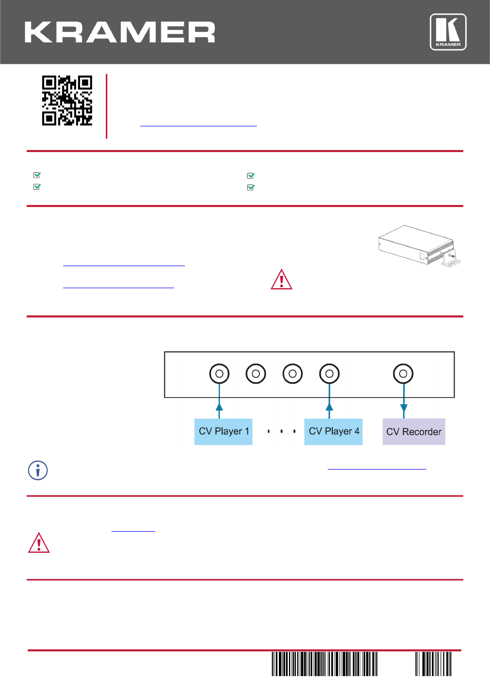
The rear panel of the
4x1V
has RCA
connectors (shown here).
The
4x1VB
has BNC connectors.
To achieve specified extension distances, use the recommended Kramer cables available a
Using third-party cables may cause damage!
Step 4: Connect power
Connect the power cord to
4x1V, 4x1VB
and plug it into the mains electricity.
Safety Instructions (Se
or updated safety information)
Caution:
•
For products with relay terminals and GPI\O ports, please refer to the permitted rating for an external connection, located next to the terminal or in the User Manual.
•
There are no operator serviceable parts inside the unit.
Warning:
•
Use only the power cord that is supplied with the unit.
•
Disconnect the power and unplug the unit from the wall before installing.
Step 5: Operate 4x1V, 4x1VB
Press one of the switcher input selector buttons to select the input that switches to the output.