TP-Link EAP225 AC1350 Wireless Dual-Band Gigabit Ceiling Mount Access Point User Manual
Quick installation guide, Hardware overview 1, Hardware installation 2
Quick Installation Guide
Wireless Access Point
Setup with videos
Visit https://www.tp-link.com/support/setup-video/ or scan the QR code to search for
the setup video of your product model.
Note
: The image may differ from the actual product.
Hardware Overview
1
Solid Green
: The device is initializing or working properly.
Solid Yellow
: The device is in an isolated state.
Flashing Yellow
: The device is working abnormally.
Flashing Yellow, Green
:
The device is updating. Do not disconnect or power off the device.
Quickly Flashing Yellow, Green
: The device is being reset to its factory default settings.
LED Indicator
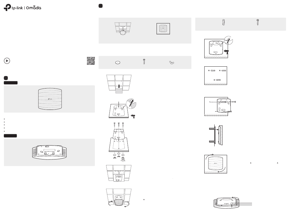
Note: Make sure that the ceiling tile is bigger than the EAP.
The EAP can be ceiling-mounted or wall-mounted. Choose a mounting method according to your needs. Follow the
steps below for the appropriate installation.
Front Panel
Rear Panel
Option1: Ceiling Mounting
Option2: Wall Mounting
The port is used to connect to the PoE port of the provided PoE adapter or a PSE (Power Sourcing Equipment),
such as a PoE switch, for both data transmission and Power over Ethernet (PoE) through Ethernet cable.
ETH1 (PoE) (For EAP225 / EAP245 / EAP265 HD )
The port is a Gigabit Ethernet port used for bridging.
ETH2 (For EAP245 / EAP265 HD)
The port is used to connect to a router or a switch to transmit data, or to a PSE (Power Sourcing Equipment), such
as a PoE switch, for both data transmission and Power over Ethernet (PoE) through Ethernet cable.
ETHERNET (For EAP110 / EAP115)
Plug one end of the provided power adapter to this port and the other end to a standard electrical wall outlet to
power the EAP.
POWER (For EAP115)
With the device powered on, press and hold the button for about 5 seconds until the LED is quickly flashing
yellow then green, then release the button. The device will restore to factory default settings.
RESET
Option 1: Ceiling Mounting
Option 2: Wall Mounting
Wing Nuts (Qty.3)
Washers (Qty.3)
M3×30 Pan-head Screws (Qty.3)
2
Place the mounting bracket in the center of the ceiling tile.
Mark three positions for the screw holes and a position for
the Ethernet cable hole.
Drill three 4 mm diameter holes for the screws and a 25 mm
diameter hole for the Ethernet cable at the marked
positions.
1
Remove the ceiling tile.
3
Secure the mounting bracket to the ceiling tile using three
M3x30 pan-head screws, washers and wing nuts, as shown
on the left.
4
Feed the Ethernet cable through the hole and set the ceiling
tile back into place.
5
Connect the Ethernet cable to the ETHERNET port. Attach
the EAP to the mounting bracket by aligning the arrow mark
on the EAP with the arrow mark on the mounting bracket,
then rotate the EAP until it locks into place, as shown on the
left.
Drill Hole for Ethernet cable
X3
Note: For security reasons, it is not recommended to install the EAP with the louver downward.
M3×20 Self-tapping Screws (Qty.3)
M3×28 Plastic Wall Anchors (Qty.3)
2
Insert the plastic wall anchors into the 6 mm diameter
holes.
3
Secure the mounting bracket to the wall by driving the
self-tapping screws into the anchors. Make sure that the
shoulders of the mounting bracket are on the outside.
4
Connect the Ethernet cable to the Ethernet port on the
EAP.
5
Attach the EAP to the mounting bracket by aligning the
arrow mark on the EAP with the arrow mark on the
mounting bracket, then rotate the EAP until it locks into
place, as shown on the left.
1
If your Ethernet cable feeds through the wall, you can
position the mounting bracket to make the cable
through the fixing hole. Mark three positions for the
screw holes and then drill three 6 mm diameter holes at
the marked positions.
X3
To remove the EAP from the mounting bracket, insert a paper clip in the Security Slot to release the Locking Tab
and rotate the EAP until it is detached from the mounting bracket, as shown below.
Tip:
Security Slot
Locking Tab
Hardware Installation
2