Profibus dp communications, Connection diagrams, Rs t c1100 – Nexen RSTC1100 964528 User Manual
Page 4
1
FORM NO. L-21230-B-0908
PROFIBUS DP COMMUNICATIONS
Profi bus is a common control bus designed for effi cient data exchange of fi eld devices on a single network. The
RSTC1100 is a slave intended to communicate with a Profi bus DPV1 master device, typically a PLC, PC, or HMI.
Profi bus DP defi nes fast, cyclic communication with distributed devices such as I/O, valves and drives. Profi bus
DPV1 offers acyclic communication services for parameter data exchange, generally used with more intelligent
devices. The RSTC1100 offers all of its parameters through acyclic data exchange, while the selection for cyclic
exchange is very limited.
Note: This manual assumes the user is familiar with Profi bus networks and the setting up of these networks.
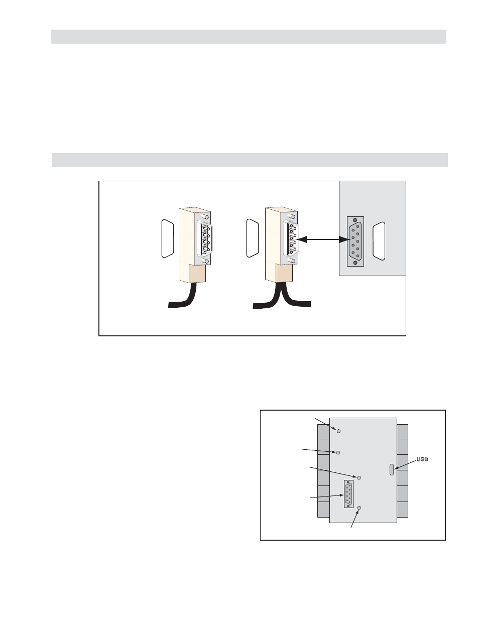
CONNECTION DIAGRAMS
The baud rate, which designates the message transmission speed in units of bits per second, can be up to 12 Mbps.
The RSTC1100 is confi gured to automatically detect baud rate from the network. Thought must be given to the
tradeoff between baud rate and cable length because a faster baud rate requires a shorter communications cable
length. The Profi bus standard specifi es a shielded, twisted pair copper cable using one conductor pair.
Recommended Cables:
Siemens
6XV1 830 0AH10
Belden
3079A
Operation Mode Indicator
Off: Not online/No power
Green: Online, data exchange
Flashing Green: Online, clear
Flashing Red (1 fl ash): Parameterization error
Flashing Red (2 fl ashes): Profi bus Confi guration error
Status Indicator
Off: No power or not initialized
Green: Initialized
Flashing Green: Initialized, diagnostic event present
Red: Exception error
Power Indicator
Reset
Operation Mode
Indicator
Status Indicator
Profibus Port
R
S
T
C1100
Figure 2
1
2
3
4
5
6
7
8
9
1
2
3
4
5
6
7
8
9
1
2
3
4
5
6
7
8
9
Profibus Cable
To Profibus Master Control
Termination Style
Node Style
9-Pin D-sub
Male
9-Pin D-sub
Male
9-Pin D-sub
Female
9-Pin Profibus Connector
Pin1 = Shield
Pin 3 = B
Pin 8 = A
RSTC1100
Figure 1