Modbus rs485 communications – Nexen RSTC1000 964523 User Manual
Page 4
1
FORM NO. L-21208-C-0908
MODBUS RS485 COMMUNICATIONS
NOTE: This manual assumes familiarity with the Modbus RTU over Serial Line protocol. If you are not
familiar with this protocol, then the following documents must be read: Modbus Application Protocol
Specifi cation and Modbus over Serial Line Specifi cation & Implementation Guide found at http://www.
modbus.org.
Modbus RTU is a master/slave protocol that allows the RSTC1000 to send information only after it has been re-
quested from the master device, typically the RSTC Operator Panel (ROP), Programmable Logic Controller (PLC),
or Human Machine Interface (HMI). There can be up to 247 devices on one network all communicating with just one
master. Each device on the network must share the same communication settings and have a unique address in the
range of 1 to 247 with the exception of the master, which does not require an address.
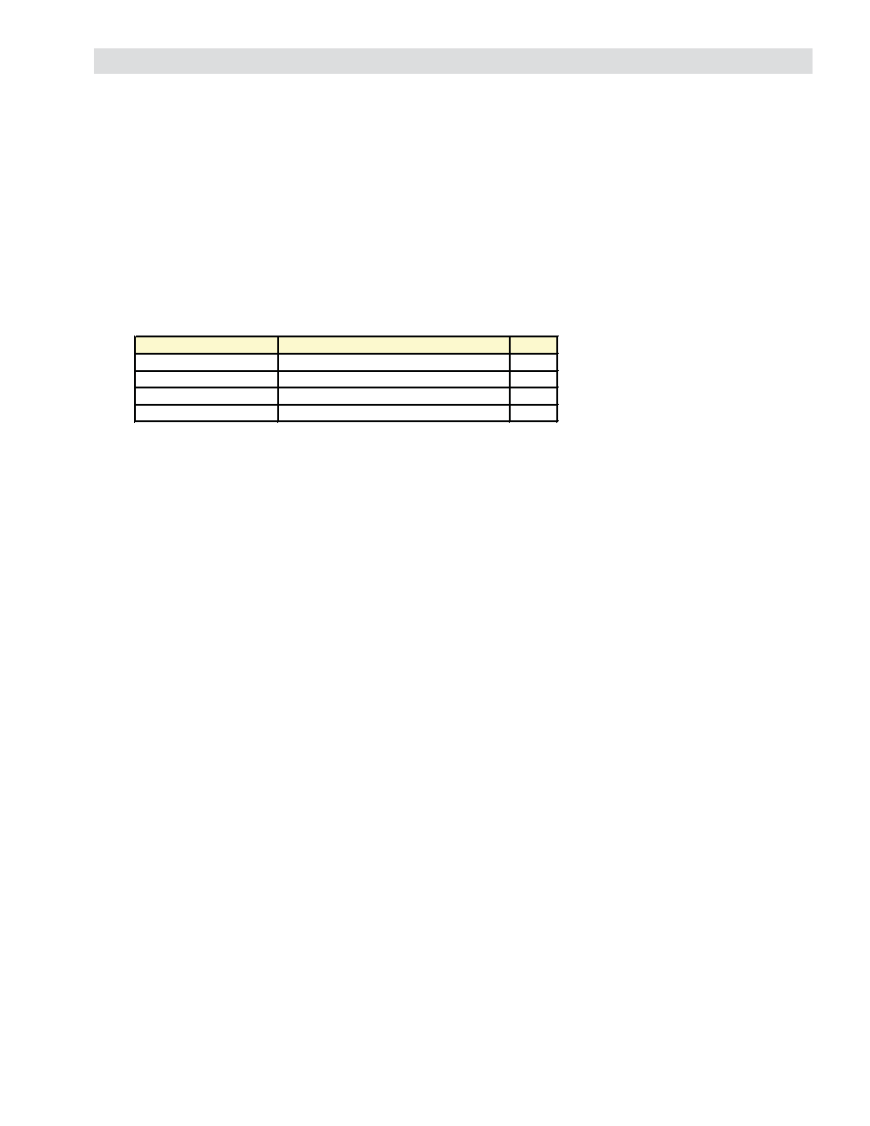
The RSTC1000 Modbus RTU communication settings are as follows:
These settings can be changed via the RSTC Communications Software, or must fi rst be used by the master to es-
tablish communication with the RSTC1000 and then changed as desired. The ROP has been programmed with the
same communication parameters and will, upon connecting to the RSTC1000, be able to communicate without any
changes. Because the ROP is a master device there can be no other masters on the same Modbus network.
Any address in the range of 1 to 247 can be assigned to the RSTC1000.
Baud rates, which designate the message transmission speed in units of bits per second, can be set for 4800,
9600, 14400, 19200, 38400, or 56000. The larger the baud rate the less time it takes for a message to travel
across the network and the less time a device spends sending or receiving the message. However, the trade off is
typically reduced communication cable length. The Modbus standard specifi es the maximum communication cable
length as 1000 meters using a 4-wire implementation (500 meters for a 2-wire implementation), 26 AWG or larger
wire, shielded, at 9600 baud. Cable capacitance and wire resistance affect baud rates, and as cable lengths in-
crease so does the capacitance and resistance. This can cause a reduction in the speed that a message can travel
across the network.
Each message byte that is sent using the Modbus RTU protocol is eleven bits long with the message data byte being
eight bits and then encapsulated by three other bits: start, parity, and stop. The start bit marks the beginning of the
message byte. Parity is used for error detection and is often not necessary as another error detection method, Cycli-
cal Redundancy Checking (CRC), is also performed on the message byte to check for errors. The stop bit marks the
end of the message byte.
Parity can be set for none, odd, or even.
Stop Bits must be set to 1 for use with odd or even parity or 2 for use with no parity.
Load Termination Resistors (LTR) are necessary to reduce noise and are applied to the devices at the remote ends of
the network. These resistors can be installed at the RSTC1000’s Modbus RS485 port connector (refer to Figure 1).
Typical values for LTRs are 150 ohms and 0.5 watts.
Settings Options Default
Network Address Range 1 to 247
24
Baud Rates
4800, 9600, 14400, 19200, 38400, 56000
19200
Parity
none, odd, even
None
Stop Bits
1 (odd or even parity), 2 (no parity)
2