Altera Arria V GX User Manual
Page 19
Chapter 4: Starter Board Setup
4–3
Factory Default Switch Settings
November 2014
Altera Corporation
Arria V GX Starter Kit
User Guide
To restore the switches to their factory default settings, perform the following steps:
1. Set DIP switch bank (SW1) to match
2. Set DIP switch bank (SW2) to match
3. Set DIP switch bank (SW3) to match
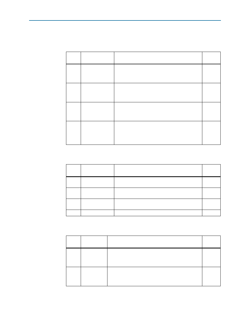
Table 4–1. SW1 Dip Switch Settings
Switch
Board
Label
Function
Default
Position
1
PCIE_PRSNT_X1
Switch 1 has the following options:
■
When ON, x1 presence detect is enabled.
■
When OFF, x1 presence detect is disabled.
ON
2
PCIE_PRSNT_X4
Switch 2 has the following options:
■
When ON, x4 presence detect is enabled.
■
When OFF, x4 presence detect is disabled.
ON
3
PCIE_PRSNT_X8
Switch 3 has the following options:
■
When ON, x8 presence detect is enabled.
■
When OFF, x8 presence detect is disabled.
ON
4
FAN FORCE ON
Switch 4 has the following options:
■
When ON, a logic O is selected, fan is turned on. (Fan
is not included in this kit.)
■
When OFF, logic 1 is selected, fan is turned off.
OFF
Table 4–2. SW2 Dip Switch Settings
Switch
Board
Label
Function
Default
Position
1
5M2210_JTAG_EN
Set to OFF to include the MAX V System Controller in
the JTAG chain. Default is OFF (in chain).
OFF
2
HSMA_JTAG_EN
Set to OFF to include HSMC Port A in the JTAG chain.
Default is ON (not in chain).
ON
3
PCIE_JTAG_EN
Set to OFF to include the PCI Express Edge Connector in
the JTAG chain. Default is ON (not in chain).
ON
4
—
—
—
Table 4–3. SW3 Dip Switch Settings (Part 1 of 2)
Switch
Board
Label
Function
Default
Position
1
USER0
Switch 1 has the following options:
■
When ON, a logic 0 is selected.
■
When OFF, a logic 1 is selected.
OFF
2
USER1
Switch 2 has the following options:
■
When ON, a logic 0 is selected.
■
When OFF, a logic 1 is selected.
OFF