Applied Motion 3540M User Manual
Page 3
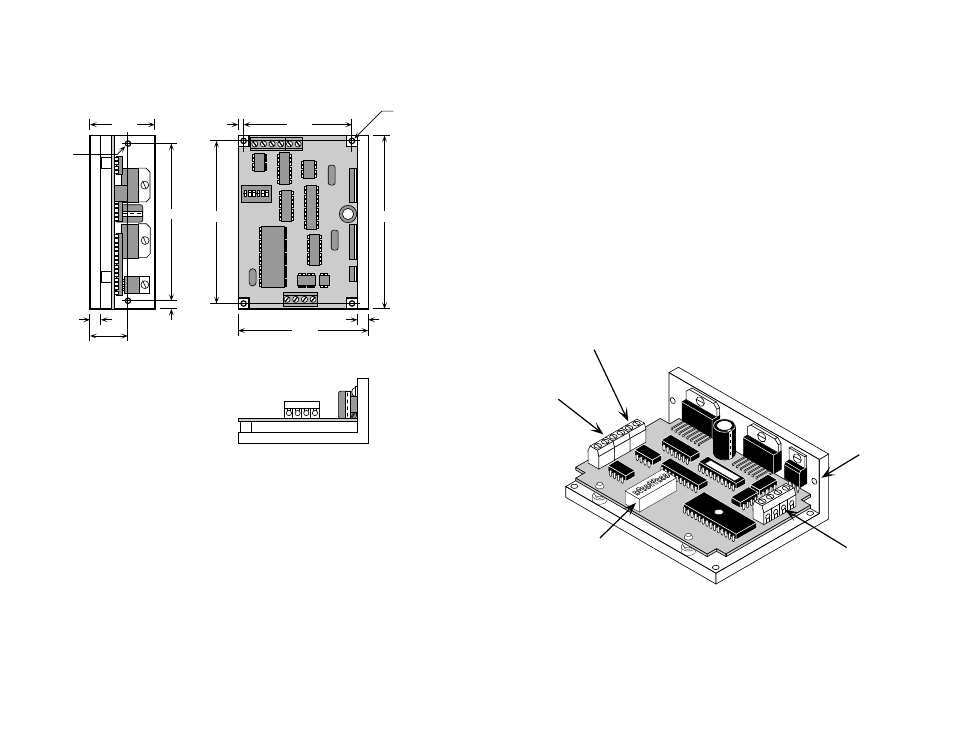
logic
connector
(
STEP, +5, DIR, EN)
mounting
hole (1 of 6)
power
connector
motor
connector
switches for
selecting current,
step resolution,
self test
-3-
-14-
Mechanical Outline
2.50"
3.75"
0.125"
3.00"
0.25"
4.00"
0.15"
4x Ø.125
3.70"
1.50"
0.25"
.875"
2x Ø.125
Getting Started
To use your Applied Motion Products motor control, you will need the following:
• a 12-42 volt DC power supply for the motor. Please read the section entitled
Choosing a Power Supply for help in choosing the right power supply.
• +5 volts DC, 15mA to activate the optoisolation circuits (if you don't use 5 volt
logic, see page 6.) This is provided by most indexers and PLCs.
• a source of step pulses capable of sinking at least 5 mA
• if your application calls for bidirectional rotation, you'll also need a
direction signal, capable of sinking 5 mA
• a compatible step motor
• a small flat blade screwdriver for tightening the connectors
The sketch below shows where to find the important connection and adjustment
points. Please examine it now.