Applied Motion 3540M User Manual
Page 6
-11-
-6-
DIR
STEP
+5V
Drive Input Circuit
680
680
680
EN
50% IDLE
4
4
50% IDLE
Idle Current Reduction
Selected
No Current Reduction
Idle Current Reduction
Your drive is equipped with a feature that automatically reduces the motor current
by 50% anytime the motor is not moving. This reduces drive heating by about 50%
and lowers motor heating by 75%. This feature can be disabled if desired so that
full current is maintained at all times. This is useful when a high holding torque is
required. To minimize motor and drive heating we highly recommend that you
enable the idle current reduction feature unless your application strictly forbids it.
Idle current reduction is enabled by sliding switch #4 toward the
50% IDLE label,as
shown in the sketch below. Sliding the switch away from the
50% IDLE label
disables the reduction feature.
TEST
1
1
TEST
Self Test ON
Self Test OFF
Self Test
The 3540 M includes a self test feature. This is used for trouble shooting. If you
are unsure about the motor or signal connections to the drive, or if the 3540 M isn't
responding to your step pulses, you can turn on the self test.
To activate the self test, slide switch #1 toward the
TEST label. The drive will
slowly rotate the motor, 1/2 revolution forward, then 1/2 rev backward. The pattern
repeats until you slide the switch away from the
TEST label. The 3540 M always
uses half step mode during the self test, no matter how you set switches 2 and 3.
The self test ignores the
STEP and DIRECTION inputs while operating. The
ENABLE input continues to function normally.
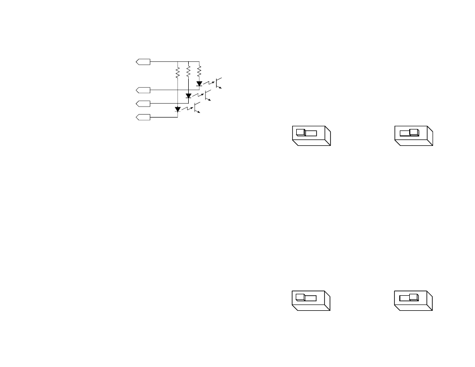
Your controlling logic must be capable of
sinking at least 5 mA to control each drive
input. Most CMOS and open collector TTL
devices are directly compatible with this drive.
Logic low, or 0, for a given input occurs when
that input is pulled to less than 0.8 volts DC.
In this state the LED is conducting current.
Logic high, or 1, occurs when the input is
greater than 4 volts or open.
STEP tells the driver when to move the motor one step. The drive steps on the
falling edge of the pulse. The minimum pulse width is 0.5 microseconds.
DIRECTION signals which way the motor should turn. See the step table on page 8
for details. The
DIRECTION signal should be changed at least 2 microseconds
before a step pulse is sent. If you change the state of the direction input
and send a step pulse at the same instant the motor may take a step in
the wrong direction.
ENABLE allows the user to turn off the current to the motor by setting this signal to
logic 0. The logic circuitry continues to operate, so the drive "remembers" the step
position even when the amplifiers are disabled. However, the motor may move
slightly when the current is removed depending on the exact motor and load
characteristics. If you have no need to disable the amplifiers, you don't
need to connect anything to the
ENABLE input.
Using Logic Voltages other than 5 volts DC
The 3540 M was designed to be used with 5 volt CMOS and TTL logic signals. To
prevent interference between the drive and the controlling logic, the input signals
are optically isolated. That means that your signals are powering LEDs within the
drive's optocoupler circuits. The LEDs require at least 5 milliamps of current to turn
on, but cannot stand more than 20 mA. Since the LEDs themselves only drop about
two volts, current limiting resistors must be used on each logic input.
A schematic diagram of the input circuit is shown below.
You must supply 5 volts DC to supply current to the LEDs on the input side of the
optoisolators. The maximum current draw is 15 mA total.