Applied Motion ST10-C-CE User Manual
St5/10-c quick setup guide, Requirements, Step 1 - wiring
ST5/10-C Quick Setup Guide
Requirements
▪
A small flat blade screwdriver for tightening the connectors (included).
▪
A personal computer running Microsoft Windows 98, 2000, ME, NT, XP, Vista or 7.
▪
▪
An RS-232 Applied Motion programming cable (included)
▪
4 pin spring connector (included) for connecting to the CAN network.
▪
A compatible stepper motor
▪
For more detailed information, please do
To begin, make sure you have the following equipment:
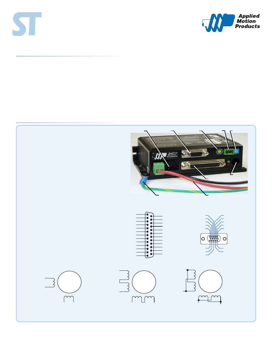
Step 1 - Wiring
920-0042 A
920-0042C
ST5/10-C Quick Setup Guide
▪
Wire the drive to the DC power source.
(Do not apply power until Step 3.)
Note, the ST5-C accepts DC voltages from 24-48V,
while the ST10-C accepts DC voltages from 24-80V.
If using an external fuse, we recommend the following:
ST5-C
: 4 amp fast acting
ST10-C
: 7 amp fast acting
See the hardware manual for information about power supply
selection.
Ensure a proper earth ground connection by using the screw
on the left side of the chassis.
POWER CONNECTIONS
BIT RATE
I/O CONNECTIONS
NODE ID
CANOpen
GROUND CONNECTION
MOTOR
ENCODER
RS232
▪
Connect the drive to the motor.
Warning - If you are using a non-Applied Motion motor,
do not connect the motor until you have configured the
drive for your motor. Refer to Step 3.
Refer to the wiring diagrams below. For details and rec-
ommended motor
▪
Connect the I/O
▪
Connect the Encoder (optional)
A+
A–
B+
B–
4
lead
motor
Red
Blue
Yellow
White
4 Leads
X COMMON
X3 / Enable
X5 / CW JOG
X4 / Alarm Reset
Analog IN
Analog IN
X2 / DIR -
X2 / DIR +
X1 / STEP+
X1 / STEP -
GND
GND
X8/CCW LIMIT -
X8/CCW LIMIT+
X7/CW LIMIT -
X7/CW LIMIT+
Y4 -
Y4+
+5V OUT
Y COMMON
Y3 / FAULT
Y2 / MOTION
Y1 / BRAKE
18
17
16
15
14
13
12
11
10
9
8
7
6
5
4
2
3
1
19
20
21
22
23
24
25
X6 / CCW JOG
IN/OUT - ST5/10 - Q/Si
Z+ (5)
NC (10)
B- (4)
NC (9)
B+ (3)
NC (13)
NC (14)
NC (15)
(12) NC
(11) NC
(6) Z-
(1) A+
(7) +5VDC 200mA
(2) A-
(8) GND
PC GND
PC TX-/RX- or B
PC TX+/RX+ or A
+RX- +TX- GND
Drive 1
Drive 2
Drive 3
+RX- +TX- GND +RX- +TX- GND
PC GND
PC RX-
PC RX+
PC TX-
PC TX+
+RX- +TX- GND
Drive 1
Drive 2
Drive 3
+RX- +TX- GND +RX- +TX- GND
Y1 / BRAKE
Y2 / MOTION
Y3 / FAULT
Y COMMON
+5V OUT
GND
Y4+
Y4-
X7 / CWLIMIT+
X7 / CWLIMIT-
X8 / CCWLIMIT+
X8 / CCWLIMIT-
ANALOG IN1
ANALOG IN2
NOT USED
X6 / CCWJOG
X5 / CWJOG
X4 / ALARM RESET
X3 / ENABLE
X COMMON
X2 / DIR-
X2 / DIR+
X1 / STEP-
X1 / STEP+
GND
1
2
3
4
5
6
7
8
9
10
11
12
13
14
15
16
17
18
19
20
21
22
23
24
25
IN/OUT
ENCODER
*Optional
A+
A–
B+
B–
8
lead
motor
8 Leads Series Connected
8 Leads Parallel Connected
A+
A–
B+
B–
8
lead
motor
Orange
Org/Wht
Blk/Wht
Black
Red Red/
Wht
Yel/
Wht
Yellow
Orange
Org/
Wht
Blk/Wht
Black
Red
Red/Wht
Yel/
Wht
Yel
low