Step 2 - canopen setup, Step 3 - configuration, St5/10-c quick setup guide – Applied Motion ST10-C-CE User Manual
Page 2: 0042c, Bit rate table
920-0042C
ST5/10-C Quick Setup Guide
Step 2 - CANOpen Setup
▪
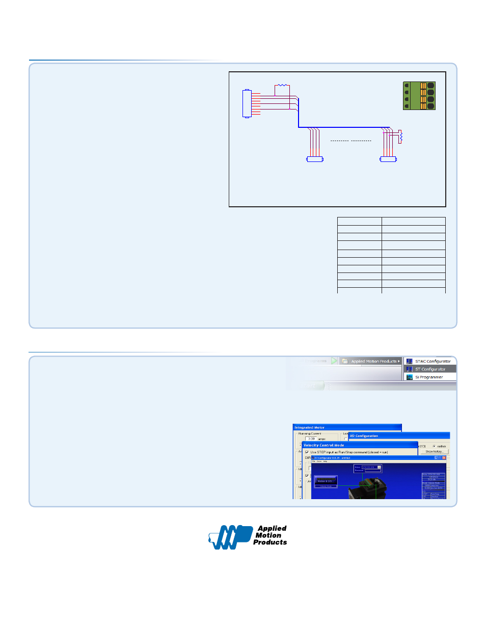
Connect to CAN network.
Applied Motion Products ST5/10-C drives use a four-pin
spring connector, that conforms to the DR303 specification.
The connector should be wired in a daisy-chain configuration
with a 120 Ohm resistor used to terminate each end.
Switch Setting
Resultant Bit Rate
0
1 Mbps
1
800kbps
2
500 kbps
3
250 kbps
4
125 kbps
5
50 kbps
6
20 kbps
7
12.5 kbps
8
n/a
9
n/a
Bit Rate Table
▪
Connect the drive to your PC using the RS-232 programming cable.
▪
▪
Launch the software by clicking Start/Programs/Applied Motion Products/ST Configurator
Step 3 - Configuration
▪
Apply power to the drive.
▪
Use the ST Configurator™ to set up the motor current, load iner-
tia, limit switches and encoder functionality (if applicable).
▪
The ST Configurator™ includes a self test option (under the Drive menu)
to verify that the ST5/10-C and motor are correctly wired and configured.
▪
When configuration is complete, exit ST Configurator™. The
drive will automatically switch to CANOpen Mode.
▪
404 Westridge Dr.
Watsonville, CA 95076
Tel: 800-525-1609
Fax: 831-761 -6544
5
5
4
4
3
3
2
2
1
1
D
D
C
C
B
B
A
A
CAN_GND
CAN_SHLD
CA
N_H
CA
N_S
HLD
CA
N_L
CA
N_GND
CAN_L
CAN_H
CA
N_H
CA
N_S
HLD
CA
N_L
CA
N_GND
Title
Size
Document Number
Rev
Date:
Sheet
of
N/A
A
CANopen Network Cable for Applied Motion Drives and Kvaser LeafLight HS
A
1
1
Monday, November 24, 2008
Title
Size
Document Number
Rev
Date:
Sheet
of
N/A
A
CANopen Network Cable for Applied Motion Drives and Kvaser LeafLight HS
A
1
1
Monday, November 24, 2008
Title
Size
Document Number
Rev
Date:
Sheet
of
N/A
A
CANopen Network Cable for Applied Motion Drives and Kvaser LeafLight HS
A
1
1
Monday, November 24, 2008
n*
R termination:
Network must be terminated
at each end with a 120 ohm
resistor.
n:
Cable may be made with up to 254
drive connectors. Termination is
only required at each end.
CAN_BUS
DSUB9 Female
DSUB9 Female
1
2
3
4
5
6
7
8
9
.1" Spacing Spring Plug
.1" Spacing Spring Plug
4 3 2 1
R termination*
120 ohm nominal
R termination*
120 ohm nominal
.1" Spacing Spring Plug
.1" Spacing Spring Plug
4 3 2 1
R termination*
120 ohm nominal
R termination*
120 ohm nominal
▪
Set BitRate, Node ID
CANOpen Bitrate - AMP CANOpen drives have three settings, one for Bit Rate and two for Node
ID. The Bit Rate is configured using an eight-position switch. See Bit Rate table for the Bit Rate
settings. The Node ID is configured using a sixteen position switch to set up the lower four bits
of the Node ID. The upper three bits of the Node ID are set using an additional 8 position switch
located under the cover on the CANOpen motherboard. Valid ranges for the Node ID are 0x01
through 0x7F. Node ID 0x00 is reserved in accordance with the DS301 specification.
Note: The Node ID and Bit Rate are captured only after a power cycle, or after a network reset
command has been sent. Changing the switches while the drive is powered on will NOT change
the Node ID or Bit Rate until one of these conditions has been met.
GND
CAN_L
SHLD
CAN_H