2 x1 & x2 inputs, Txm24c – Applied Motion TXM24C-1CG User Manual
Page 15
15
Rev. D
920-0088
TXM24C Hardware Manual
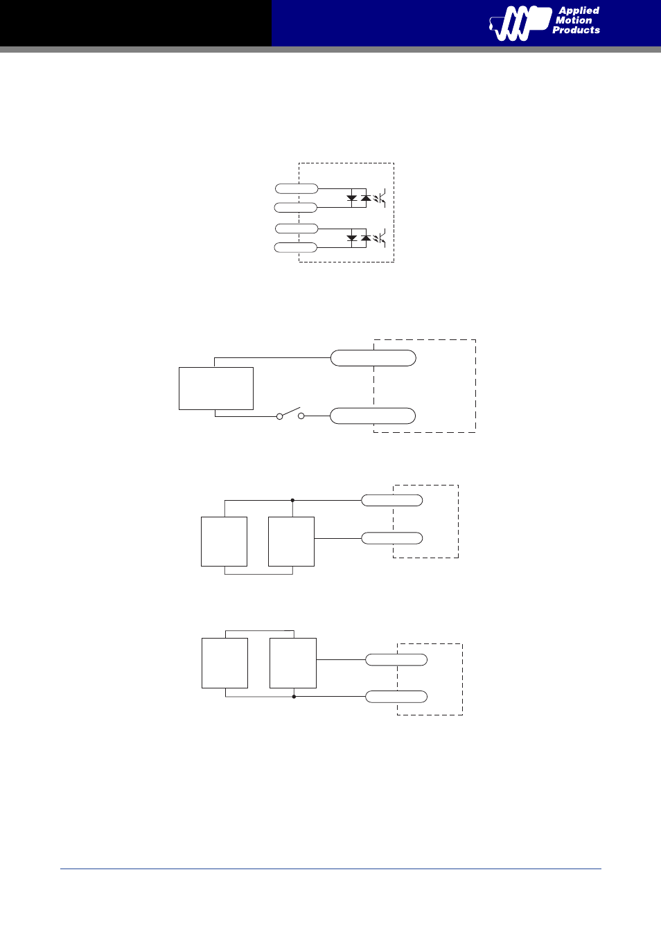
3.3.2 X1 & X2 Inputs
X1 and X2 digital inputs are designed operation between 5 and 24 volts. The diagrams below
show how to connect them to various commonly used devices like sensors, switches, relays,
PLCs, etc.
Note: If current is flowing into or out of an input, the logic state of that input is low or
closed. If no current is flowing, or the input is not connected, the logic state is high or
open.
inside drive
M12 I/O Connector
X2+
X2-
8
5
X1+
X1-
3
1
Connecting a Mechanical Switch to Low Speed Differential Inputs
TXM24C
+
-
X1/X2-
X1/X2+
5-24V
Power Supply
Connecting an NPN Proximilty Sensor to Low Speed Differential Inputs
TXM24C
+
DC
Power
Supply
–
NPN
Proximity
Sensor
output
+
–
X1/X2-
X1/X2+
Connecting a PNP Proximilty Sensor to Low Speed Differential Inputs
TXM24C
+
DC
Power
Supply
–
PNP
Proximity
Sensor
output
+
–
X1/X2-
X1/X2+