Programmable outputs, 35 sv7 hardware manual – Applied Motion SV7-C-CE User Manual
Page 35
35
SV7 Hardware Manual
920-0012F
12/18/2014
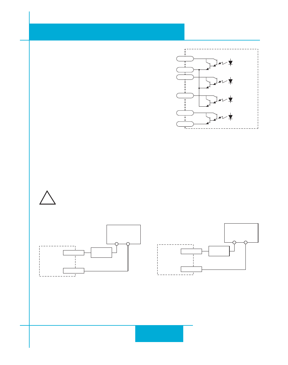
Programmable Outputs
The SV drives feature four digital outputs. These outputs
can be set to automically control a motor brake, to signal
a fault condition, to indicate when the motor is moving or
to provide an output frequency proportional to motor
speed (tach signal). Or the outputs can be turned on and
off by program instructions like Set Output.
Note: an electric brake cannot be connected directly
to the programmable output of the SV. A relay must
be added between the output and brake coil. See
example relay wiring diagrams below.
The outputs can be used to drive LEDs, relays and the inputs of other electronic devices like PLCs
and counters. For OUT4, the “+” (collector) and “-” (emitter) terminals of each transistor are avail-
able at the connector. This allows you to configure each output for current sourcing or sinking. The
OUT1-3 outputs can only sink current. The COM terminal must be tied to power supply (-).
Diagrams of each type of connection follow.
Do not connect the outputs to more than 30VDC.
The current through each output terminal must not exceed 80 mA.
IN/OUT1
YCOM
Y1/2/3
5-24 VDC
Power Supply
+
–
Load
IN/OUT1
Y1
YCOM
Y3
Y2
14
17
15
20
21
16
Y4+
Y4-
Sinking Output
Using Y4
IN/OUT1
Y4-
Y4+
5-24 VDC
Power Supply
+
–
Load
Sinking Output
Y1, Y2 or Y3
!