Motor test, Input/output connector wire colors – Applied Motion BD10-H4-AH User Manual
Page 15
15
BD5/10 Drive Hardware Manual
920-0065D
2/14/2014
Motor Test
• Ensure that DIP switch 1 is ON and 2 is OFF (to use internal power supply
for I/O). Note, it may be necessary to remove the external cover to access the internal DIP switches. It may also
be possible to access these switches by carefully reaching through the slots with the small screw driver that is
included.
• Speed and accel/decel settings are controlled by on-board potentiometers, adjustable using the included
screwdriver.
• Plug in both connectors of matching BL motor.
• Apply power to the drive.
• TESTING: To start the motor spinning, connect STP (pin11, black/white)
to GND (pin2) and adjust the SPD pot to the desired speed. To reverse
direction, connect CW/CCW (yellow) to GND (pin2).
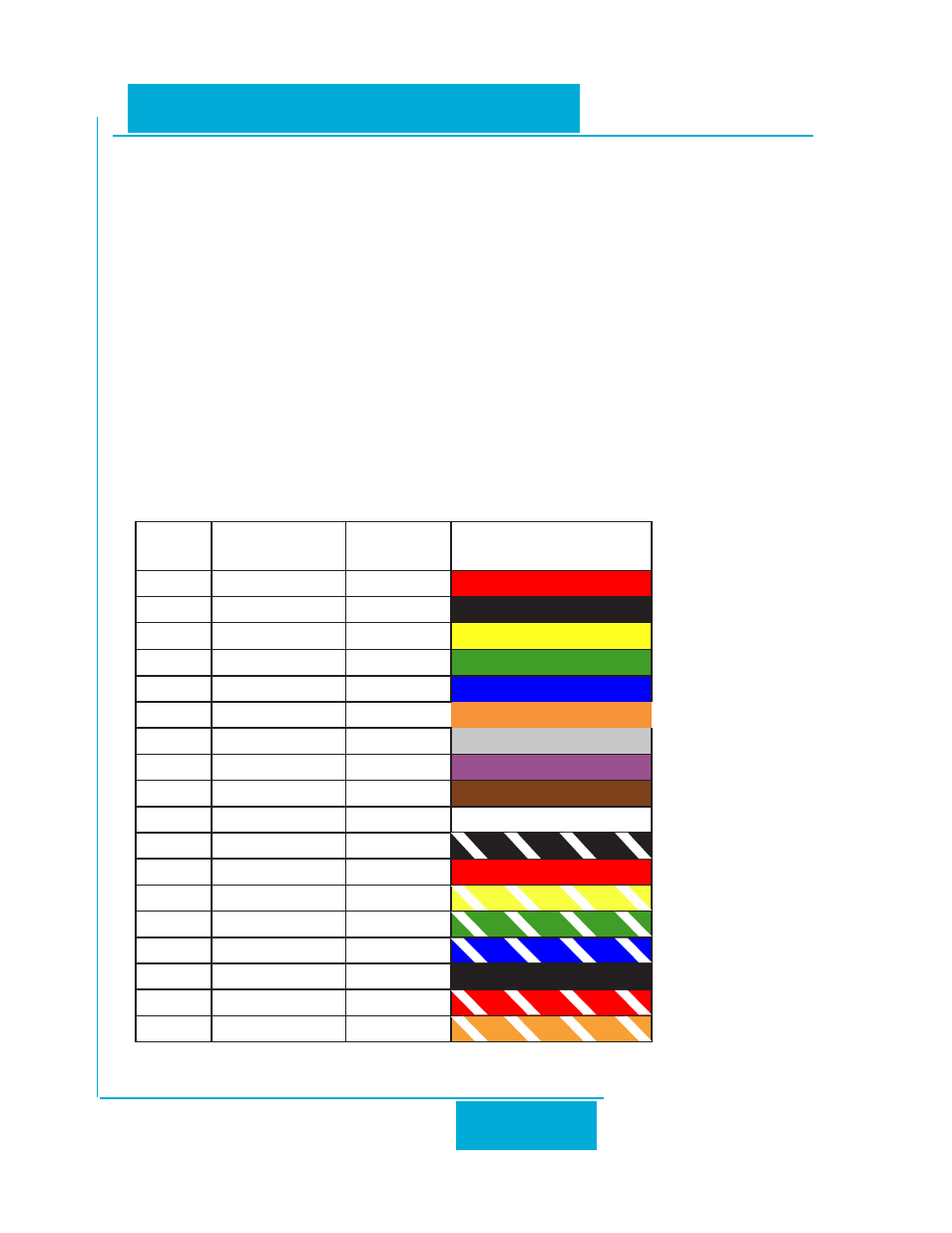
Input/Output Connector Wire Colors
The signal names and colors used on the I/O cable provided with each drive are as shown below:
BD5/10
PIN
BD5/10 FUNC-
TION
COLOR
COLOR CODE
1
5V
RED
2
GND
BLK
3
CW/CCW
YEL
4
FLT+
GRN
5
STMD
BLU
6
FLT-
ORG
7
EN/RE
GRY
8
SPO+
VIO
9
SPST
BRN
10
SPO-
WHT
11
STP
BLK/WHT
12
5V
RED
13
M0
YEL/WHT
14
AIN
GRN/WHT
15
M1
BLU/WHT
16
AGND
BLK
17
M2
RED/WHT
18
INCOM
ORG/WHT