Mating connectors and accessories, Connector diagrams – Applied Motion BD10-H4-AH User Manual
Page 35
35
BD5/10 Drive Hardware Manual
920-0065D
2/14/2014
Connector Diagrams
I/O Connector
Motor Connectors
1
3
5
7
9
11
13
15
17
2
4
6
8
10
12
14
16
18
INCOM
AGND
AIN
FLT-
SPO-
SPO+
FLT+
GND
5V
M2
M1
M0
STMD
SPST
EN/RE
CW/CCW
5V
STP
CN4
5V
HB
HA
GND
HC
CN3
U
V
W
CN2
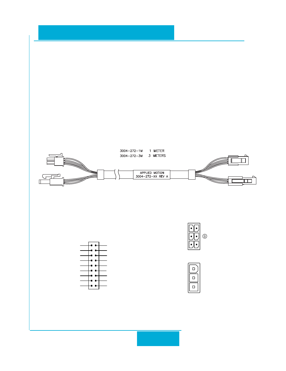
Mating Connectors and Accessories
Mating Connectors
I/O: Housing: JST PUDP-18V-S. Crimp contacts: SPUD-001T-P0.5. Flying lead cable included with drive.
Power supply: PCD ELFP0221G (Phoenix Contact 1757019), included with drive.
Motor: Molex 39-01-2060 housing with Molex 39-00-0039 pins, included with motor.
Hall Signals: Molex 43025-0600 housing with Molex 43030-0001 pins, included with motor.
Accessories
Motor Extention Cable, 1 meter: 3004-272-1M
Motor Extension Cable, 3 meters: 3004-272-3M
Regeneration Clam
Model PSP-600-48 : We recommend a 600 watt 48 VDC power supply for use where 200 watt or 300 watt
motors are used to their full capability or where many drives will be connected to one power supply.