Ab 2 – Atlona AT UHD EX 100CE User Manual
Page 7
7
atlona.com
Toll free: 1-877-536-3976
Local: 1-408-962-0515
Captive Screw
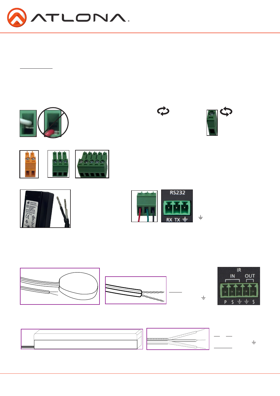
Connecting
Captive screw connectors are an added feature on the UHD extender. The captive screw connectors allow you
to cut cables down to a suitable length, reduce cable clutter, while providing a more reliable connection.
The captive screw connectors have
a contact bar that is adjusted to
compress the wire against the top
contact plate. Use the screws at the
top of the connector to compress the
wire against the contact plate.
When connecting the cables to the female captive screw connector it is important that the wires be
terminated correctly. The female captive screw connector has a contact plate at the top and must have the
wires touching it for signal to pass. When wired correctly
(see picture A)
the signal will pass, incorrectly
(see
picture B)
no signal will pass.
Female captive screw connectors are included: Power
(see picture 1)
,
RS-232
(see picture 2)
, and IR
(see picture 3)
.
The power cable
(picture
4)
will have exposed
wires. Each wire is
encased in a different
colored cover.
1
Power
RS-232
Clockwise
Counter
Clockwise
Turn the screws clockwise to
raise the contact bar to the
upper contact plate and hold
the wires in place.
Turn the screws counter
clockwise to lower the
contact bar to release the
wires.
A
B
2
RS-232 pin out will be
determined by the RS-232
cable and will connect as Rx
(receiver)
, Tx
(transmitter)
, and
(ground)
.
(See picture 5)
Pin out color will differ
per RS-232 cable.
Black: - White: +
- +
4
5
Note: The IR receiver is optional for the UHD-EX-100CE-KIT and RX box. The compatible IR receiver (AT-IR-CS-RX) can
be purchased through atlona.com.
The wires of the emitter and receiver have been marked to differenciate the pin outs.
The included IR emitter has two wires: signal and ground. Signal will have a solid line and ground will be
blank. The IR emitter will plug into the IR OUT ports.
There are three wires on the IR receiver
(
AT-IR-CS-RX sold separately
)
: signal, ground, and power. Signal has a
dotted line, ground will be blank, and power will have a solid line. The IR receiver will plug into the IR IN
ports.
IR
3
Signal (S)
Ground (
)
Signal (S)
Ground (
)
Power (P)