Operation and control – Atlona AT RGB MATRIX User Manual
Page 18
17
www.atlona.com
Toll free: 1-877-536-3976
Local: 1-408-962-0515
OPERATION AND CONTROL
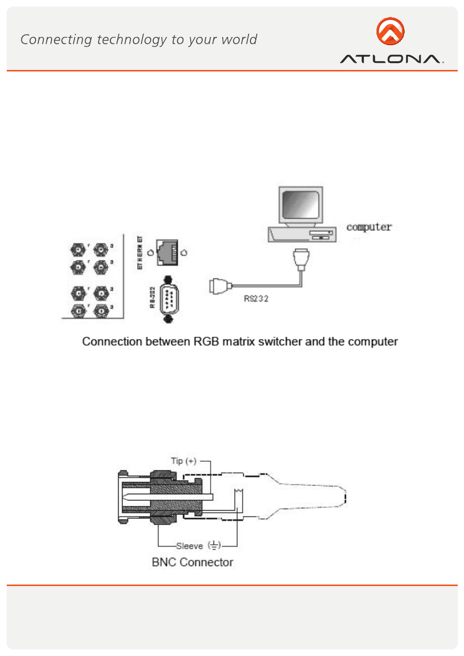
The Switchers can be controlled by front controls or PC, third party automation and control systems, SWITCHER
2.0 control system software or through the Ethernet control via the RS-232 communication port. The RS232
is a female 9-pin D connector. It can be switched by several control systems. When the switcher connects to
the COM1 or COM2 of the computer with control software, users can control it by that computer. To control
the switcher, users may use the application SWITCHER 2.0 in the supplied CD or develop their own control
software.
The RGB / Component matrix switchers may take DVD players, computers and graphic workstations as their
input signal source, and projectors, video recorders, displays and amplifiers as their output signal depending
on different applications. RGBHV connection: The RGB matrix switchers supports the AV video and VGA signal
sources. RGBHV signal output terminals or YC output terminals are needed in the AV device; RGBHV signal
output terminals are needed in the VGA device. The BNC connector is shown as the figure below. If switching
Component Video and 2-channel analog audio, utilize the existing H/V inputs and outputs with the supplied
BNC to RCA adapters for connecting the audio inputs and outputs.