Rear panel – Atlona AT LINE PRO5 User Manual
Page 5
www.atlona.com | toll free:
1-877-536-3976
For International: 1-
408-962-0515
5
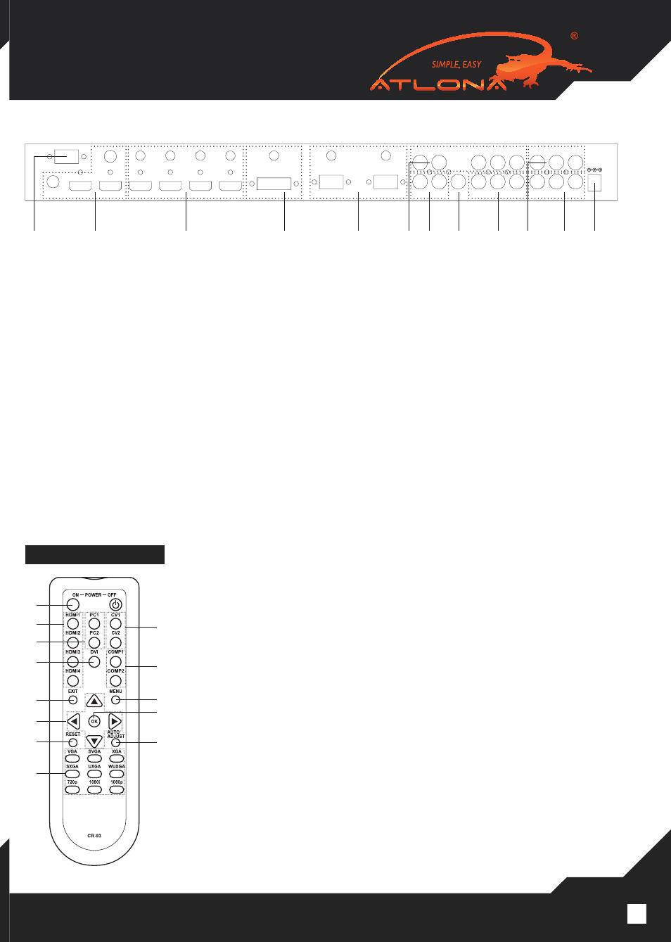
6.2. Rear Panel
1. RS-232: This port could be used between a 3rd party control system for control purposes or a computer for
firmware updates.
2. HDMI & Coaxial Out 1~2: These ports are to connect to HD Display and or Projector for displaying the output
signal. The DVI/HDMI adapter can be used if the display has DVI input. Each HDMI output is accompanied
with Coaxial audio output in case if DVI display is being used or HDMI is only used for video. The HDMI
will contain audio and video signal no matter separate audio output is used or not.
3. HDMI IN 1~4 & L/R: These ports are to connect input sources such as Blu- ray players, Cable Boxes, Comput-
ers with HDMI or DVI outputs. If user has a DVI source, the 3.5mm audio input will allow to embed audio
4. DVI IN & L/R: This port is to connect to computer video sources. The DVI port is accompanied with mini stereo
audio input.
5. VGA IN 1~2 & L/R: These slots are to connect input sources such as Laptop, Desktop Computers, Document
Camera or any other VGA source. Each VGA input is accompanied with mini stereo audio input.
6. Y/PB/PR & L/R 1~2: These ports are to connect input sources such as DVD player, Cables Boxes or HD Cam-
era. Each Component input is accompanied with stereo audio input.
7. CV & L/R: These ports are to connect to input sources such as VCR or Security Camera. Each Composite
input is accompanied with stereo audio input.
8. COAX/Spdif: This port is to connect any source with S/PDIF audio output to a scaler. S/PDIF input could be
assigned to any video input under On Screen Didplay.
9. DC 5V: This port is to connect to a supplied power supply.
REMOTE CONTROL
1. POWER ON/OFF: Press these buttons to power on the device or to set it
to standby mode.
2. HDMI1~4: Press to select HDMI inputs 1~4.
3. PC 1~2: Press to select VGA inputs1/2.
4. DVI 1: Press to select DVI input source.
5. CV 1~2: Press to select Composite Video input.
6. COMP1~2: Press to select Component video inputs 1/2.
7. MENU: Press to bring up On Screen Display.
8. Exit: Press to exit from a sub menu or main menu.
9. ▲/▼/◄/►: Press ▲/▼ to move the highlight bar to your desired param
eter during the On Screen Display operation. Press ◄/► to increase/ de
crease the setting value of a selected parameter.
10. OK (Enter): Press to confirm your selection.
11. Reset: Press the button to reset the unit’s firmware setting to the factory
default.
12. Auto Adjust: Press to optimize the position of the picture (picture centering)
on the screen.
13. Output Resolution: Press to directly select output resolution. For other out
put resolutions that are not available on the remote please enter On Screen
Display Menu to select them.
DC 5V
CV1
CV2
R
R
L
L
R
L
COAX
Cr/Pr Cb/Pb Y/HD2
Cr/Pr Cb/Pb Y/HD1
R
L
VGA 1
VGA 2
L/R
L/R
L/R
L/R
L/R
L/R
L/R
DVI1
HDMI 4
HDMI 3
HDMI 2
HDMI 1
HDMI OUT
HDMI OUT
COAX OUT
COAX
OUT
RS-232
②
①
⑥
⑦
③
④
⑤
⑥
⑧
⑥
⑦
⑨
①
②
③
④
⑧
⑨
⑪
⑬
⑤
⑥
⑦
⑫
⑩