Pin definitions – Atlona AT HDSDI AV User Manual
Page 8
Advertising
6
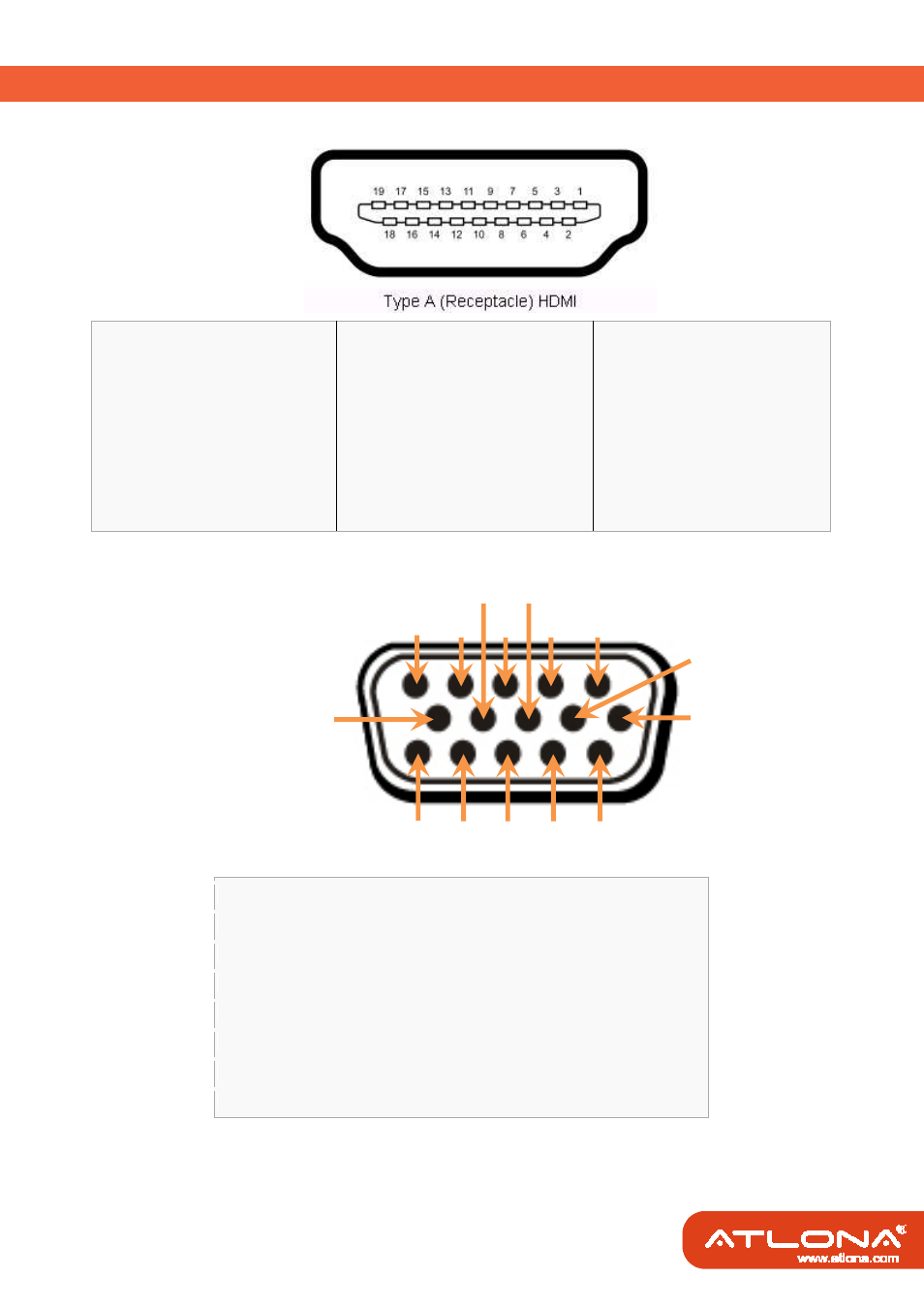
PIN DEFINITIONS
HDMI
™
Pin 1
TMDS Data2+
Pin 8
TMDS Data0 Shield
Pin 15
SCL
Pin 2
TMDS Data2 Shield Pin 9
TMDS Data0–
Pin 16
SDA
Pin 3
TMDS Data2–
Pin 10
TMDS Clock+
Pin 17
DDC/CEC Ground
Pin 4
TMDS Data1+
Pin 11
TMDS Clock Shield
Pin 18
+5 V Power
Pin 5
TMDS Data1 Shield Pin 12
TMDS Clock–
Pin 19
Hot Plug Detect
Pin 6
TMDS Data1–
Pin 13
CEC
Pin 7
TMDS Data0+
Pin 14
Reserved
VGA and Component
Pin 1
Pr / Red
Pin 9
+5 V
Pin 2
Y / Green / Composite
Pin 10
Ground
Pin 3
Pb / Blue
Pin 11
Ground
Pin 4
Ground
Pin 12
Reserved
Pin 5
Ground
Pin 13
Horizontal sync.
Pin 6
Ground
Pin 14
Vertical sync.
Pin 7
Ground
Pin 15
Reserved
Pin 8
Ground
1
2
3
4
5
10
6
7
8
9
11
12
13
14
15
Advertising