Panel description, Front panel, Back panel – Atlona AT HDCAT V2 User Manual
Page 4: Number of leds will vary by hdcat device
4
atlona.com
Toll free: 1-877-536-3976
Local: 1-408-962-0515
AT-HDCAT-8
AT-HDCAT-8
AT-HDCAT-8
DC 24V
BACK UP
MAIN
DC 24V
FIRMWARE
1
2
3
4
HDMI 1
INPUT
OUTPUT
OUTPUT
HDMI 2
ANALOG
L
- +
-
+
R
SPDIF
HDMI
5
6
8
7
5
6
7
8
4
AT-HDCAT-8
1
2
3
B
M
EDID
AUTO
AUTO
INT LEARN
INPUT
POWER SYNC LOCK
1 2
AT-HDCAT-8
DC 24V
BACK UP
MAIN
DC 24V
FIRMWARE
1
2
3
4
HDMI 1
INPUT
OUTPUT
OUTPUT
HDMI 2
ANALOG
L
- +
-
+
R
SPDIF
HDMI
5
6
8
7
5
6
7
8
4
AT-HDCAT-8
1
2
3
B
M
EDID
AUTO
AUTO
INT LEARN
INPUT
POWER SYNC LOCK
1 2
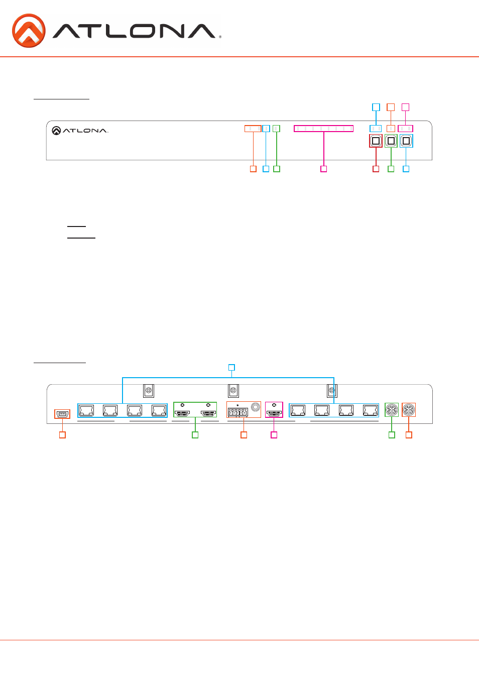
Panel Description
Front Panel
1. Power LED - Red LED will illuminate to display connected power supplies. M is main. B is back up.
2. Sync LED - Blue LED indicates it is receiving signal from the selected source.
3. Lock LED - When the function keys are locked the blue LED will illuminate
Lock - Press the Input button and hold for 5 seconds. All function keys will lock.
Unlock - Press the Input button and hold for 5 seconds. All function keys will unlock.
4. Output LED - Blue LED will light up for each output connected and sending signal.
*Number of LEDs will vary by HDCAT device
5. Input Button - Press to manually switch between sources.
6. Auto Button - Press to activate or deactivate the smart switching feature.
**This feature auto-detects incoming source signals and switches to the corresponding input
7. EDID Button - Press to switch between internal and learned EDID™ options.
8. HDMI
®
LED - Blue LED will illuminate to indicate the current active input.
9. Auto LED - Blue LED will light up when the auto switching feature is enabled.
10. INT/Learn LED - Blue LED will illuminate to indicate EDID operational status (INT or Learn).
1
1
3
6
4
2 3
2
7
5
4
5
6
7
8
9
10
Back Panel
1. Firmware port - Field serviceable USB port for updating firmware.
2. HDMI input - Connect HDMI sources here
3. De-embedded audio - Connect audio from these ports to a local audio receiver or amplifier.
4. Local HDMI output - Local output for in room display, AVR, or HDCAT cascading.
5. Back up power port - Connect second optional power supply (AT-PW24V6.25A - sold separately)
6. Main power port - Connect main power supply to this port.
7. CAT5e/6/7 Output - Connect to a receiver (purchased separately @ atlona.com) to pass signals
over extended distances.
Ex. Optional receivers AT-HDRX for 230ft with all HDCAT products. For extended distance with the AT-HDCAT-8ED use
AT-HDRX-RSNET (328ft)