Panel description, Transmitter receiver – Atlona AT HDTXRX ROADNET User Manual
Page 4
4
ETHERNET
HD VIDEO LINK OUT
DC 24V
FIRMWARE
LINK
POWER
RS232
IR IN
HDMI IN
AT-HDTX-ROADNET
PWR IR
RX TX
IR OUT
- +
TX
ETHERNET
HD VIDEO LINK IN
FIRMWARE
LINK
POWER
RS232
IR IN
HDMI OUT
AT-HDRX-ROADNET
PWR IR
RX TX
IR OUT
- +
RX
ETHERNET
HD VIDEO LINK OUT
DC 24V
FIRMWARE
LINK
POWER
RS232
IR IN
HDMI IN
AT-HDTX-ROADNET
PWR IR
RX TX
IR OUT
- +
TX
ETHERNET
HD VIDEO LINK IN
FIRMWARE
LINK
POWER
RS232
IR IN
HDMI OUT
AT-HDRX-ROADNET
PWR IR
RX TX
IR OUT
- +
RX
atlona.com
Toll free: 1-877-536-3976
Local: 1-408-962-0515
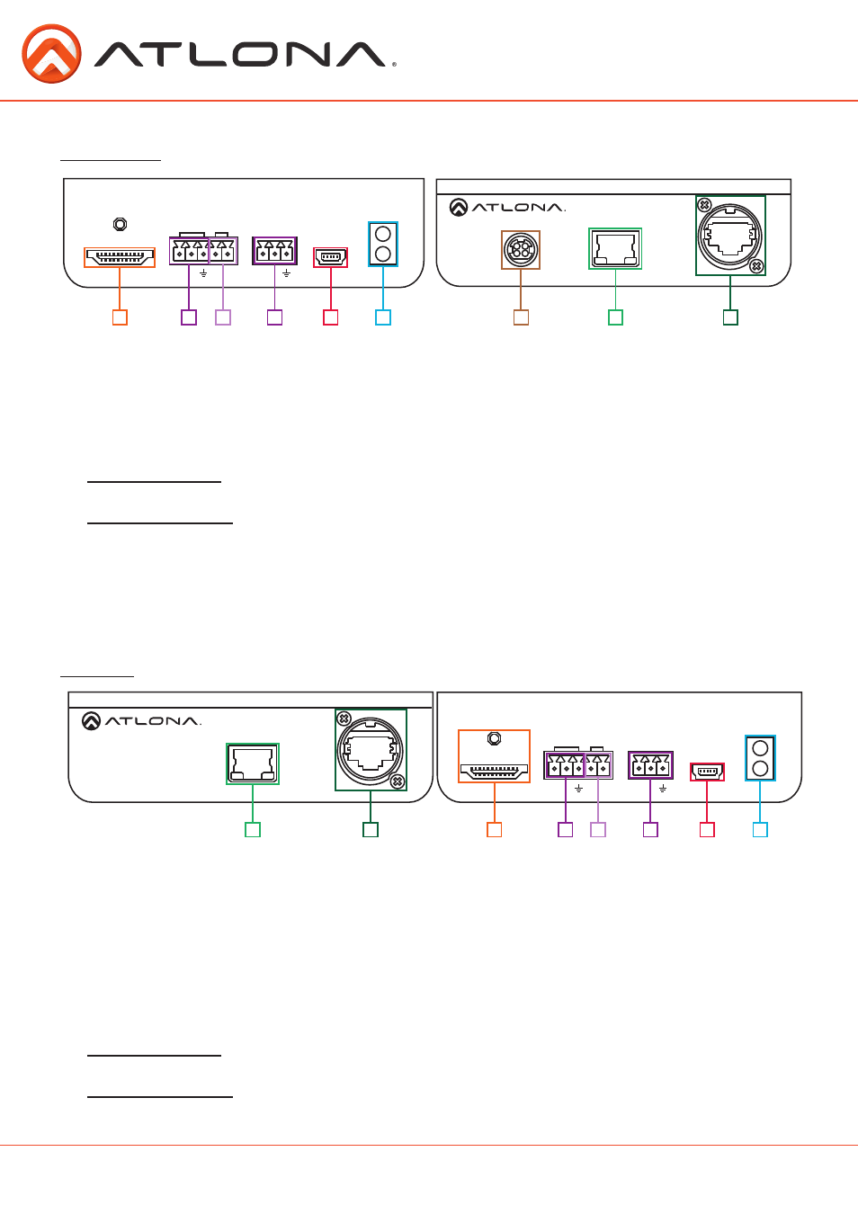
Panel Description
Transmitter
Receiver
1. HDMI IN Port: Connect HDMI or DVI (with adapter) source here.
2. IR IN Port: Connect an IR receiver or IR control box to this port.
3. IR OUT Port: Connect the IR Emitter or IR control box to this port.
4. RS232 Port: Bidirectional RS-232, send signal to or from a control system or PC
5. Firmware Update Port: Use a mini USB to USB A cable to connect to a Windows computer for
updating.
6. Yellow Link LED: Signal Indicator for the HD VIDEO LINK OUT port. LED will remain solid, unless
there is an issue with the cable or signal, then it will blink.
Green Power LED: Power indicator. If plugged in light will remain solid. If LED starts blinking
power is intermittent or there is a problem with the cable. If LED is off, no power is passing to
the receiver (check your outlet or the power cable).
7. DC 24V Port: Connect included quick release power adapter here.
8. Ethernet: Send a signal to a display or source from a network
9. HD VIDEO LINK OUT Port: Connect a category cable with an etherCON
TM
connector from here
to a compatible receiver.
1. Ethernet: Send a signal to a display or source from a network.
2. HD VIDEO LINK IN Port: Connect a category cable with an etherCON
TM
connector from a
compatible transmitter to this port.
3. HDMI OUT Port: Connect to HDMI or DVI (with adapter) display.
4. IR IN Port: Connect the IR receiver to this port.
5. IR OUT Port: Connect the IR Emitter to this port.
6. RS232 Port: Bidirectional RS-232, send signal to or from a control system or PC.
7. Firmware Update Port: Use a mini USB to USB cable to connect to a Windows computer for
updating.
8. Yellow Link LED: Signal Indicator for the HD VIDEO LINK IN port. LED will remain solid, unless
there is an issue with the cable or signal, then it will blink.
Green Power LED: Power indicator. If plugged in light will remain solid. If LED starts blinking
power is intermittent or there is a problem with the cable. If LED is off, no power is passing to
the receiver (check your outlet or the power cable).
8
9
2
5
4
7
6
7
6
8
2
4
1
3
1
3
5