Captive screw, 35 6 7 a b c – Atlona AT HDTXRX ROADNET User Manual
Page 5
5
For greater distance and IR rejection from plasma, CFL, and LED
panels, purchase the AT-IRX-CS (IR receiver) through atlona.com
Includes black, silver, and white bezels.
atlona.com
Toll free: 1-877-536-3976
Local: 1-408-962-0515
Captive Screw
Connecting
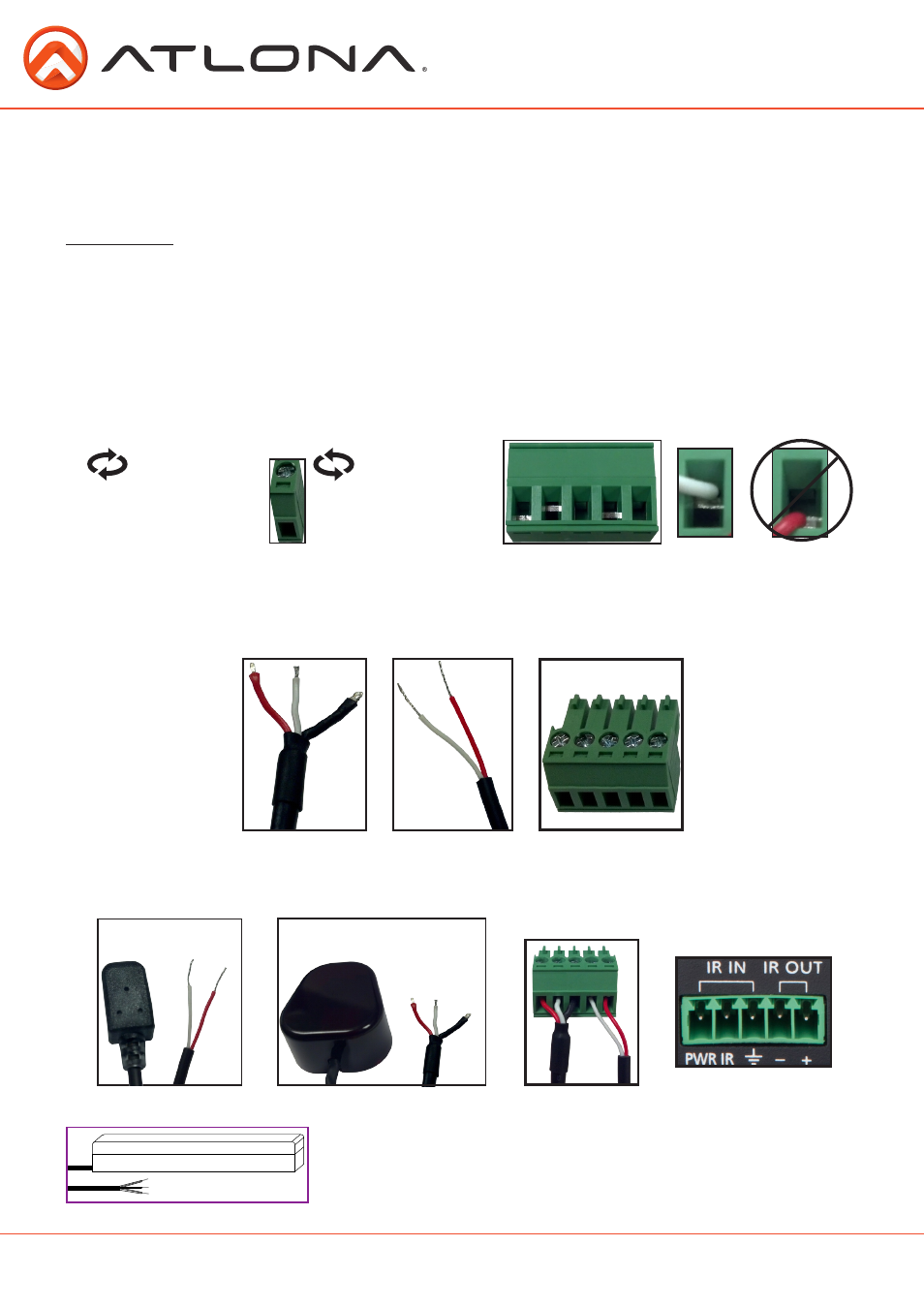
Captive screw connectors are an added feature on the HD Extenders. The captive screw connectors allow
you to cut cables down to a suitable length, reducing cable clutter, and provides a more reliable connection.
The captive screw connectors have a contact bar that is moved to compress the wire to the top contact
plate. Use the screws at the top of the connector to compress the wire against the contact plate.
When connecting the cables to the female captive screw connector it is important that the wires be
terminated correctly. The female captive screw connector (see picture A) has a contact plate at the top and
must have the wires touching it for signal to pass. When wired correctly (see picture B) the signal will pass,
incorrectly (see picture C) no signal will pass.
For your convenience the cables do not come pre-terminated. Each item, whether it’s an IR receiver (picture
1) or IR emitter (picture 2), will have wires exposed. Each wire is encased in a different colored jacket. A
female captive screw connector for IR is included.
IR pin outs have been included for the included IR emitter and IR receiver (see picture 6 & 7). The wires are
colored for each pin (see picture 8 and 9).
White: - Red:+
Red: PWR White: IR Black:
╧
2
1
IR
Clockwise
Counter
Clockwise
Turn the screws clockwise to
raise the contact bar to the upper
contact plate and hold the wires
in place.
Turn the screws counter clockwise
to lower the contact bar to release
the wires.
3
5
6
7
A
B
C
-
+
Emitter
PWR IR
╧
Receiver
4