Set-point entry, Alarm messages – BINDER C 150 User Manual
Page 7
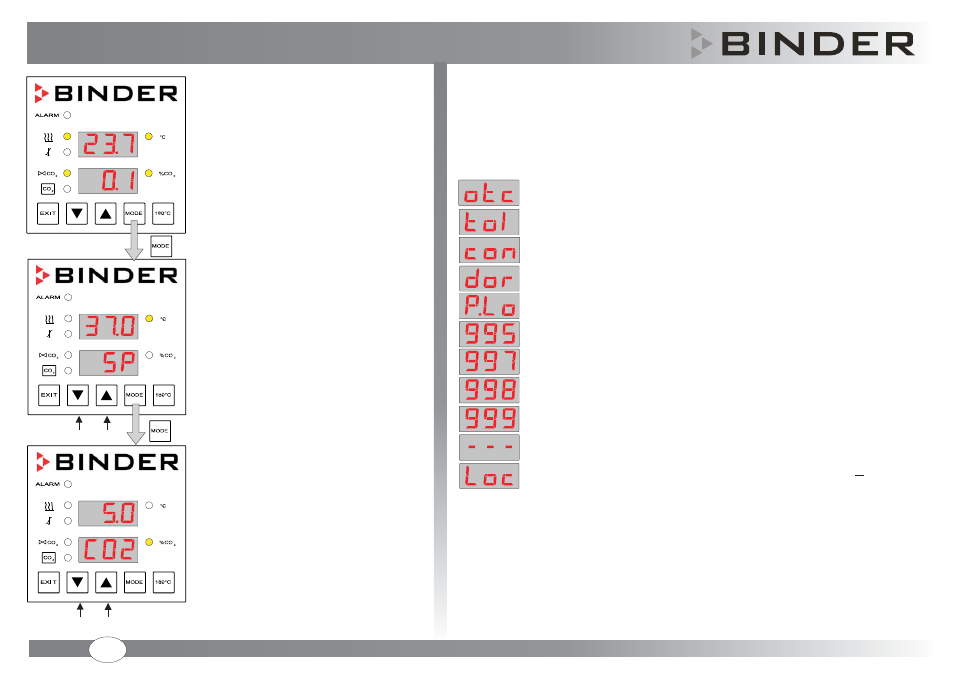
Set-point entry
Set-point entry temperature
Normal Display
D
actual
values of
concentration
isplay of the
temperature
and CO
2
Set-point entry temperature and CO
2
Set-point entry, confirm with "Mode"
Copyright
BINDER GmbH
10/2012
Art. No. 7001-0235
©
O
HAND
perating mode
Set-point entry
CO
2
Set-point entry
Set value of the safety controller exceeded
Temperature tolerance range alarm
CO tolerance range alarm
Door open
CO pressure too low
Failure of CO sensor
Failure of temperature sensor for door heating
Failure of temperature sensor for safety controller
Failure of temperature sensor for interior heating
2
2
2
CO sensor not connected
Sterilization program started with operating mode HAND locked (LOCK)
Sterilization program started with the CO sensor still plugged-in.
2
2
or
When operational faults occur, the controller triggers visual and audible alarm signals. The LED “ALARM”
(general alarm) lights up.
If more than one alarm signal is sent simultaneously, they are displayed in a cycle. Alarms 995 to 999 take
priority over all other displays of the controller.
Alarms are displayed immediately when the fault occurs. After opening the unit door or switching on the
C 150, tolerance range alarms are suppressed for the selected delay times.
Resetting the alarm messages
Zero-voltage relay alarm output
The maximum loading capacity of the switching contacts must NOT exceed 24 V AC/DC 2.5 Amp.
Eliminate the cause of the alarm or wait until the unit compensates for the error. The visual alarm
disappears, when the cause of the fault has been remedied or the monitored operating function returns
within its tolerance limits. Press the “EXIT” button to switch off the audible alarm signals.
The zero-voltage relay alarm output permits transmission of the alarm e.g., to a central monitoring system.
Alarm messages
GB