Specification – Casella CEL CEL-254 User Manual
Page 2
INTRODUCTION
The CEL-231 Digital Sound Survey Meter
has been designed to meet the sound survey
requirements of Safety Engineers and
Occupational Nurses, while the more powerful
CEL-254 Digital Impulse Sound Level Meter is
designed for Industrial Safety Officers.
These specialists require inexpensive and
easily used instruments to check whether
industrial noise exposure areas require a more
detailed investigation.
Both instruments satisfiy the requirements
of the international and national IEC 651 Type 2,
BS EN 60651 : 1994 Type 2, and ANSI S1.4
Type 2A standards for both free field and
random incidence sound level meters. The
CEL-254 also satisfies the requirements of IEC
651 Type 2I for impulse sound level meters.
The instruments provide a clear and
unambiguous digital indication of the
A-weighted sound level on an easily read
display. They feature the standard Fast and
Slow time weightings, and can measure sound
levels between 30 dB(A) and 135 dB(A) in two
ranges, at frequencies between 10 Hz and 20
kHz.
In addition, the CEL-254 can indicate
C-weighted sound levels and overload
conditions, includes a standard Impulse time
weighting with reset function, indicates battery
voltage on the display, and has a maximum hold
function that operates with all time constants.
Conditioned a.c, and logarithmic d.c outputs
are available from a single standard 3.5 mm 3
pole coaxial socket in both instruments, so they
may be used with level/time and tape recording
systems.
A complete CEL-231 Sound Survey Meter
consists of the following items.
CEL-231
Sound Survey Meter,
032460/DP
Microphone Cover,
016022 (4 off) Type AAA Manganese
Alkaline Battery,
038055
Screwdriver,
060064/HB
Instructions.
(1) Gently squeeze the clips
(2) Then pull apart .
1
2
1
01014
+
(4 x Type IEC AAA
Alkaline Batteries)
2 Batteries
2 Batteries
01015
+
Calibr
ator
CEL
-254
Measurement Mode SPL
Switch
Microphone Coupler
Turn
Screwdriver
Range A Hi (or C Hi)
Time Weighting F (Fast)
01016
Tape or DAT
Recorder
Level Recorder
C4964/2 Cable
C4963/2 Cable
01017
A complete CEL-254 Digital Impulse Sound
Level Meter consists of the following items.
CEL-254
Digital Impulse SLM,
032460/DP
Microphone Cover,
016022 (4 off) Type AAA Manganese
Alkaline Battery,
038055
Screwdriver,
060064/HB
Instructions.
The following accessories may be ordered
separately to enable the user to gain the
maximum advantage from the instrument.
CEL-284/2
Acoustical Calibrator Class 1L
(complete with CEL-4725
Microphone Coupler),
CEL-282
Acoustical Calibrator Class 2L
(complete with CEL-4725
Microphone Coupler),
C4963/2
Tape Recorder Cable (2 m)
with 3.5 mm jack plug & BNC
plug for a.c output,
C4964/2
Level Recorder Cable (2 m)
with 3.5 mm jack plug & BNC
plug for d.c output.
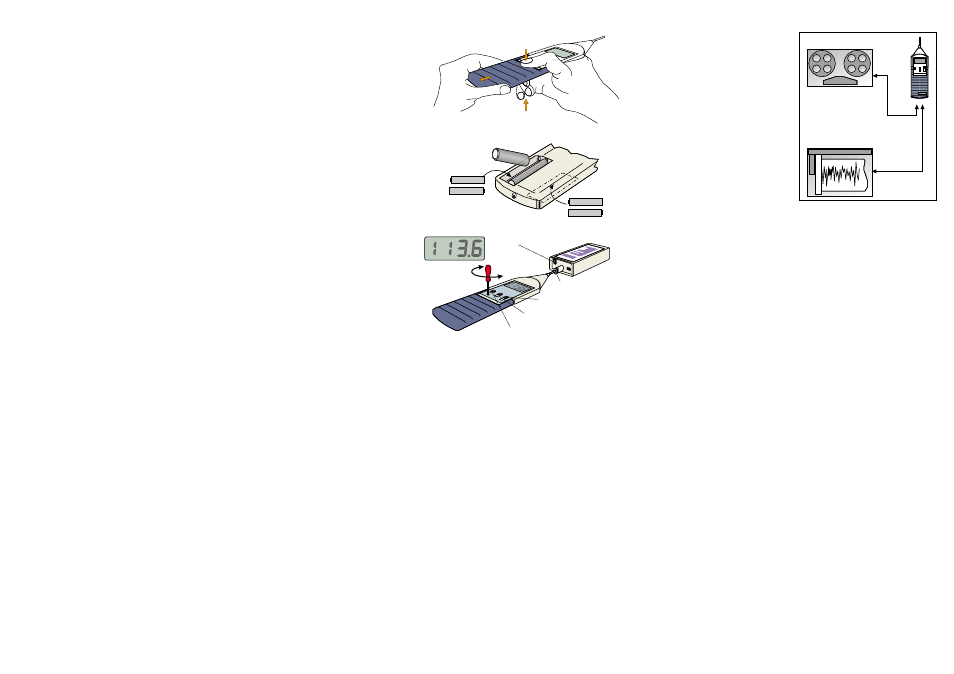
PREPARATION FOR USE
Install four type AAA Manganese Alkaline
batteries and the instrument is ready for use.
Zinc carbon batteries are NOT suitable.
The two battery compartments are exposed
when the coloured cover is removed as shown.
One compartment in the front of the instrument
inner case houses two batteries, with an
identical compartment at the back.
Observe the battery polarities indicated in
the figure and in each compartment, and
replace batteries when LO BAT is indicated.
Having inserted a set of batteries, replace the
coloured cover and ensure that it is firmly held
by the retaining clips.
On the CEL-254, the battery voltage (x10)
can be displayed by sliding the MODE switch to
BATT.
The instrument is now ready for operation.
CALIBRATION
Perform an acoustic calibration with a
CEL-282 or CEL-284/2 Acoustical Calibrator
immediately before and after measurement as
follows.
1. Remove the Microphone Cover.
2. Fit the CEL-4725 Microphone Coupler on to
the calibrator.
3. Push the calibrator and Coupler on to the
Microphone, with the label at the top as
shown.
4. Slide the Range switch to A HI (high range).
5. Slide the Response switch to F (fast) to switch
the instrument on.
On the CEL-254, also slide the MODE switch
to SPL (sound pressure level) for normal
noise measurement.
6. Wait 20 seconds for the instrument to
stabilise.
A LO BAT message indicates that the
batteries should be changed.
On the CEL-254, battery voltage (x10) can be
indicated on the display by sliding the
MODE switch to BATT.
7. Press the bottom of the calibrator switch to
obtain the nominal 114 dB at 1 kHz.
On instruments supplied after 1-1-96, the
meter display should read 113.6 dB while on
earlier instruments it should read 114.0 dB.
8. If necessary, carefully
adjust the CAL control
with the screwdriver
provided until the
indication is correct.
Two versions of the CAL
control are found.
One uses
3
/
4
turn to give
9 dB of adjustment,
while the other has 4
turns for 12 dB.
9. Switch the calibrator OFF,
when not in use.
Other calibrators may be
used with the Sound Level
Meter, but the correct
indication will depend upon
the volume of the acoustic
coupler used, the operating
frequency, and the
calibration level.
Pistonphones are not
suitable because they
operate at low frequencies,
which produce incorrect
reading when measured
with A- or C-weighted
circuits.
It is recommended that
the calibration be verified at
at least every year. Contact
the CEL Service Department
for details.
OPERATION
1. Insert batteries as
described above.
2. Calibrate the instrument.
3. Switch the calibrator OFF.
4. Remove the calibrator and
microphone coupler.
5. Select A HI (high) Range
On the CEL-254, C HI
may also be selected.
These ranges cover sound levels between
65 and 135 dB.
6. Use F (fast response) for comparatively
stable noise, or select S (slow response) for
slowly varying noise.
On the CEL-254,
I
(impulse response) may
be selected for more rapidly varying and
impulsive noise.
Impulsive noises are captured and held on
the display as A- or C-weighted levels for
approximately 1.5 s.
Slide the RESPONSE switch to IR (impulse
reset) to clear the display for the next noise
measurement.
7. Hold the instrument comfortably in the hand
and point the microphone at the suspected
noise source.
The sound level will be displayed.
8. Select A LO (low) range when the indicated
sound level falls below 80 dB(A).
On the CEL-254, C LO may also be selected.
If OVERLOAD is indicated on the CEL-254,
reselect one of the HI ranges.
9. On the CEL-254, slide the MODE switch to
MAX (maximum hold function) to capture
and hold maximum noise levels for longer
periods using any time weighting and range.
Slide the MODE switch to SPL to clear the
display for the next measurement.
10. Switch the instrument OFF (RESPONSE
switch to OFF) when not in use.
11. Remove batteries when out of service for
longer periods.
USE WITH RECORDERS
Connection for tape and level/time recorders
(and X/Y recorders that can operate with time on
the X axis) is made via the same 3.5 mm 3 pole
coaxial socket in the bottom of the instrument,
as shown.
Connection between the sound level meter
and tape recorder is made via a C4963/2 (2 m)
Cable terminated with a BNC plug. The
connections in this cable provide a conditioned
a.c output signal proportional to indicated sound
level, with 7.25 V RMS full scale deflection.
Similarly, connection between the sound
level meter and a level/time or X/Y recorder is
made via a C4964/2 (2 m) Cable terminated with
a BNC plug. The connections in this cable
provide a logarithmic d.c output signal
proportional to the indicated sound level, with
nominally 25 mV/dB.
When recordings are to be made, it is
recommended that the sound level meter be
calibrated as described above, and that a
calibration level be incorporated into the
recording. For more detailed instructions refer to
the relevant recorder handbook.
The manufacturers reserve the right to change the contents of these instructions without notice.
Specification
Type:
Sound Level Meter according to ANSI S1.4
Type 2A, IEC 651 Type 2, and BS EN 60651
: 1994 Type 2.
The CEL-254 is also an impulse sound level
meter according to IEC 651 Type 2
I
.
Dynamic range:
70 dB.
Typical instrument frequency range:
(within +0.5 to -3 dB)
Better than 10 Hz to 25 kHz in all ranges.
Accuracy: (under reference conditions)
±1 dB.
Lowest frequency for non-linear
distortion <1 dB:
5 Hz.
CEL-231 Measurement ranges:
Range
Frequency Display
Primary Linearity*
Setting
Weighting
Range
Range IEC 651
A LO (low)
A
30-100 dB
30-90 dB
A HI (high)
A
65-135 dB
65-125 dB
Note* that the lower reading is quoted at +10
dB on noise floor. Upper reading allows crest fac-
tor 3.
CEL-254 Measurement ranges:
Range
Frequency Display Primary Linearity*
Setting
Weighting Range
Range IEC 651
A LO (low)
A
30-100 dB
30-86 dB
A HI (high)
A
65-135 dB
65-121 dB
C LO (low)
C
35-100 dB
35-86 dB
C HI (high)
C
65-135 dB
65-121 dB
Note* that the lower reading is quoted at
+10 dB on noise floor. Upper reading allows
crest factor 5.
Microphone type:
CEL quarter-inch diameter pre-polarised
electret, typically 10 mV/Pa,Microphone
permanently attached to the instrument.
The microphone meets Type 2 require-
ments for both free field and random
incidence measurement.
Impedance to be substituted for
microphone:
Not possible as microphone is permanently
attached.
Contact CEL for method of measuring
electrical performance.