Cvm-net communications, Technical specifications, Connections – CIRCUTOR CVM-NET Series User Manual
Page 2: Technical service, Cvm-net, Four cvm-net quadrants
CVM-NET
M98229901-03-14A
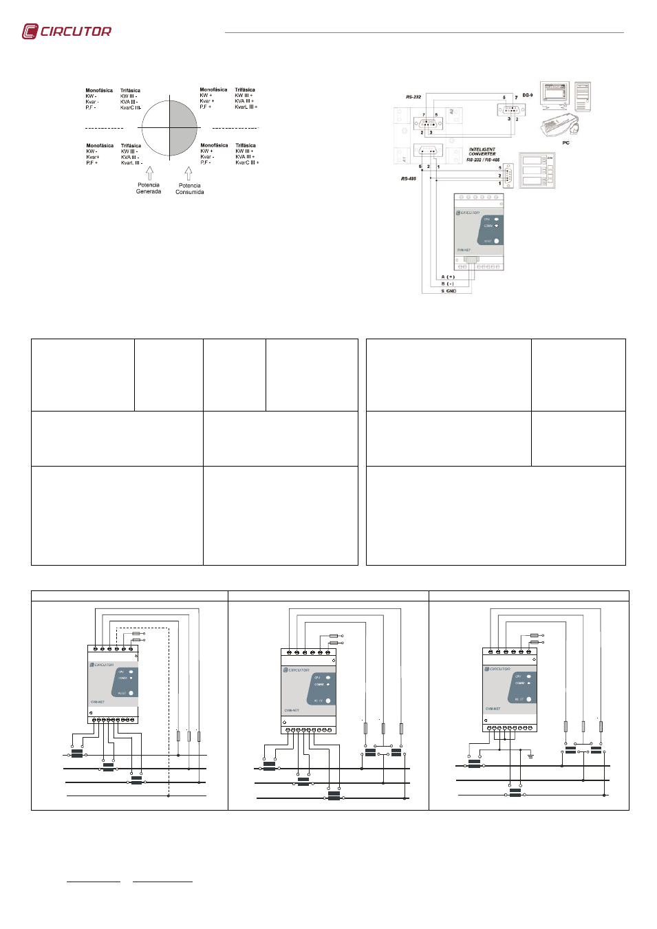
FOUR CVM-NET QUADRANTS
0º
90º
180º
-90º
Capacitivo
Capacitivo
Inductivo
Inductivo
2.7.- CVM-NET COMMUNICATIONS
One or several CVM-NET analyzers can be connected to a computer or PLC. This system
makes it possible to centralise the data in a single record point, in addition to the normal
operation of each of them (PowerStudio® System). The CVM-NET has an RS-485 serial
communication output. If more than one analyzer is connected to a serial communication bus
(RS-485), each analyzer must be assigned a peripheral number or address (from 01 to 255),
with a maximum of 32 units per communication bus, so that the central computer sends the
queries from the various records measured or calculated to these addresses.
The CVM-NET power analyzer communicates using the MODBUS RTU© protocol (Pulling
Question / Answer).
3.- TECHNICAL SPECIFICATIONS
Power circuit:
-
Single-phase:
-
Voltage tolerance:
-
Frequency:
-
Maximum consumption:
-
Working temperature:
-
Humidity (non-condensing):
AC version
230 V AC
-15% / +10%
50 - 60 Hz
3.0 V·A
-10 …..+ 50 ºC
5 ….. 95%
DC version
20…120V DC
1,2…2 W
-10 …..+ 50 ºC
5 ….. 95%
Plus version: C. & DC
85..265V AC /95..300V DC
50 - 60 Hz (AC mode.)
3.0 V·A/ 3W
-10 …..+ 50 ºC
5 ….. 95%
Metering circuit:
-
Nominal voltage: phase-neutral / between phases
-
Frequency:
-
Nominal current:
-
Permanent overload:
-
Voltage consumption of the circuit:
-
Current consumption of the circuit: ITF / Shunt
300 V AC / 520 V AC
45 ~ 65 Hz
I
n
/ 5 A
1.2 I
n
0.7 V·A
0.9 V·A / 0.75 V·A
Mechanical characteristics:
-
Case material:
-
Protection titted unit (frontal):
-
Protection non-fitted unit (sides and rear cover):
-
Dimensions (mm):
-
Weight:
V0 self-extinguishing plastic
IP 51
IP 31
85 x 52 x 70 mm (3 modules)
0.210 kg
Features of the output transistors
-
Type: Opto-isolated transistor (commutator open).
-
Maximum switching voltage:
-
Maximum switching current:
-
Maximum frequency:
-
Pulse duration:
NPN
24 V DC
50 mA
5 pulse / s
100 ms
Precisions Class:
-
Voltage:
-
Current:
-
Power / Energy:
Measurement sensors: Current / Voltage
Power factor:
Full-scale measurement margin: ITF / Shunt
Temperature sensor: Precision / Working window
-
Temperature measurement: with forced ventilation
-
Temperature measurement: without forced ventilation
Maximum altitude operating:
0.5% ± 1 digit
0.5% ± 1 digit
1% ± 1 digit
External transformers / direct voltage
0.5 to 1
0.2 ..... 120% / 2 ..... 120%
± 2 ºC / -10 ….. +50 ºC
+ 14.0 ºC
+ 3.5 ºC
2000 meters
Safety:
Category III - 300 V AC / 520 V AC EN-61010 Class II double-insulated electric shock
protection.
The system should be connected to a power supply circuit protected by fuses gl or M type,
with current ratings between 0.5 and 1 A. It should be provided with a MCCB or equivalent
device to switch off the system from the power supply circuit. The power supply and
voltage measuring circuit is connected with cable minimum cross section of 1 mm2
Standards:
IEC 664, VDE 0110, UL 94, IEC 801, IEC 348, IEC 571-1, EN 61000-6-3,
EN 61000-6-1, EN 61010-1, EN 61000-4-11, EN 61000-4-2, EN 61000-4-3,
EN 61000-4-4, EN 61000-4-5, EN 55011, CE
4.- CONNECTIONS
4 wires / 3 wires ( low voltage )
3 wires (2 voltage and 3 current transformers)
3 wires (2 voltage and 2 current transformers)
S2
P2
S1
P1
L1
L2
L3
N
S2
P2
S1
P1
S2
P2
S1
P1
N
V
L1
V
L2
V
L3
min
max Pd
max
clear
COMM
CPU
CVM-MINI
reset
reset energy
1 2 3 4 5 6 7 8 9
10 11 12 13 14 15
A
li
m
e
n
ta
c
ió
n
P
o
w
e
r
S
u
p
p
ly
S2
P2
S1
P1
L1
L2
L3
S2
P2
S1
P1
S2
P2
S1
P1
1 2 3 4 5 6 7 8 9
10 11 12 13 14 15
b
B
a
A
b
B
a
A
V
L1
V
L2
V
L3
A
lim
e
n
ta
c
ió
n
P
o
w
e
r
S
u
p
p
ly
L1
L2
L3
1 2 3 4 5 6 7 8 9
10 11 12 13 14 15
b
B
a
A
b
B
a
A
V
L1
V
L2
V
L3
S2
P2
S1
P1
S2
P2
S1
P1
A
li
m
e
n
ta
c
ió
n
P
o
w
e
r
S
u
p
p
ly
5.- TECHNICAL SERVICE
In the event of any equipment failure or any operational queries please contact the technical service of CIRCUTOR S.A.
CIRCUTOR S.A. - After sales service
Vial Sant Jordi, s/n
08232 -Viladecavalls (Barcelona)
tel - (+34) 93 745 29 00 & fax - (+34) 93 745 29 14
E-mail :