CIRCUTOR SYNCHROMAX Series User Manual
Page 2
Configuración del SynchroMax / SynchroMax configuration
Password
Pulsando ambas teclas a la vez,durante 10 segundos, permite introducir un pass
word de 4 dígitos. Éste tiene la función de inhabilitar el acceso a la configuración
del equipo. Para deshabilitarlo bastará con repetir el proceso, pero ahora el valor
introducido debe coincidir con el que lo bloqueó. El número de password es
solicitado dos veces consecutivas para evitar errores de entrada.
Valores por Defecto
Pulsando ambas teclas a la vez,durante 20 segundos, los valores de defecto
(fábrica) reempazarán a los programados.
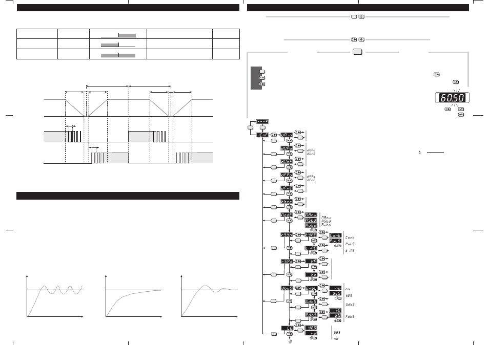
Configuración
Pulsando esta tecla durante 3 segundos, y si el password no está activado,
entraremos en el menú de configuración del equipo. Ahora, y con el uso de
las teclas, podremos navegar por el diagrama de configuración y alarmas
Acepta el valor y desplaza una posición a la izquierda en el árbol
Baja una posición en el árbol
Desplaza una posición a la derecha en el árbol
Accept value and move one position at left on the tree
Move one position down on the tree
Move one position right on the tree
Password
Pressing simultaneously both keys, during 10 second, a 4 digits password can be
set in order to control the acces configuration options. To disable this password
simply repeat the process, but now, the number introduced should be the same
that was used for enable. The password number should be entered twice in
order to avoid mistakes
Default Setup Values
Pressing simultaneously both keys, during 20 second, default setup values
replace user-configured ones.
Configuration
Pressing this key during 3 second ( and there is not any password protection)
we will enter in the configuration menu. Now, using the keyboard, we can
navigate for the configuration and alarms tree
Set
Set
Set
N
A
V
I
G
A
T
I
O
N
Introducir un valor / Setting a value
Para mover ciclicamente por los 4 digitos pulsar
Para modificar el valor del digito seleccionado pulsar repetidamente
Introducir el valor de los 4 digitos usando ambas teclas
To cyclically move along the four digits press the key
To modify the value of the selected digit repeatedly press the key
Set the desired 4 digits value using both above keys
6
7
8
Set
Set
Set
Set
Set
Set
Set
Set
Set
Set
Set
Set
Set
Set
Set
Set
Set
Set
Set
Set
Set
Set
Set
Set
Set
Set
Set
Set
Set
Set
Set
Set
Set
Set
Set
V =
Vgen - Vbb
Vbb
x 100 (%)
Min:
Def:
Max
Valor mínimo programable
Valor por defecto
: Valor máximo programable
Minimum programmable value
Default value
Maximum programmable value
= (+%) Porcentaje positivo /
(Min:1, Def:10, Max:25%)
Positive percentage
= (+Hz) Diferencia positiva /
(Min:0, Def:0.5, Max:1.0Hz)
Positive difference
= (- %) Porcentaje negativo / Negative percentage (Min:1, Def:10, Max:25%)
= (- Hz Diferencia negativa /
)
Negative difference (Min:0, Def:0.0, Max:1.0Hz)
Es posible tener un margen asimétrico, por ejemplo, aceptar que la tensión de grupo sea un 10% mayor pero sólo un 5% menor que la principal
It´s possible to have a asymmetric margin, for example, to accept that the generator voltage will be a 10% higher but only 5% lower than the busbar
Es posible tener un margen asimétrico, por ejemplo, aceptar que la frecuencia de grupo sea 1Hz mayor pero sólo 0,2Hz menor que la principal
It´s possible to have a asymmetric margin, for example, to accept that the generator frequency will be 1Hz higher but only 0.2Hz lower than the busbar
Configuración habilitada /
Configuración deshabilitada /
Enabled configuration
Disabled configuration
Valor minimo de tension principal /
(Min: 80, Def: 320, Max: 600V)
Minimum busbar voltage
Por debajo de este valor no se hará sincronización ni control de velocidad.
Under this value no synchronization neither speed control will be doned
Tiempo del contactor / Breaker response time (Min: 0, Def: 80, Max: 1000msec)
Retardo de tiempo que transcurre desde la excitación de la bobina del contactor hasta el cierre de los contactos
Delay time since the breaker coil is excited until the contacts are closed
Banda proporcional Xp / Xp Proportional band (Min: 0.2, Def:2.5, Max: 5.0Hz)
Banda de cálculo proporcional / Proportional operation band
Reles de control de velocidad / Speed control relays
Rele de sincronismo/ Synchronism relay (Def:Cont)
Función de bus muerto / Dead bus function (Def:No
)
enabled
Configuración habilitada / Enabled configuration
Conectado continuamente mientras se dan condiciones de sincro /
Duración máxima del pulso /
Conected
continuously while synchro conditions are fulfilled
Pulso mientras se dan condiciones de sincro / Pulse while s
Maximum pulse time
ynchro conditions
are fulfilled
(Min: 1, Def:1, Max: 10sec)
Función deshabilitada / Disabled function
Función habilitada / Enabled function
Máxima tensión para considerar bus muerto /
(Min: 0, Def: 0, Max: 600V)
Frecuencia de referencia para control de velocidad del generador /
(Def: 50Hz)
Maximum voltage for consider dead
bus
Reference
frequency for speed generator control
Tiempo de acción integral Tn / Tn Resetting time (Min: 200, Def:500, Max: 3000msec)
Tiempo entre dos pulsos de regulación / Time between regulation pulses
Máximo diferencia de tensión aceptable (+/- %) / Maximum acceptable voltage difference (+/- %)
Máximo diferencia de frecuencia aceptable (+/-Hz) / Maximum acceptable frequency difference (+/- Hz)
Manual
Asistida
Automática
(sólo visualiza) /
(se requiere confirmación del usuario)/
(conexión totalmente automática)/
Manual
Assisted
Automatic
(only display)
(operator confirm requested)
(completely automatic operation)
Modo de Trabajo /
( Def: MAnu)
Operation mode
Nota /
:
Mientras estemos dentro del menú de configuración quedarán desactivadas
todas las funciones del Synchromax.Por el contrario si tenemos activado el
rele de sincronismo, quedará desactivado el acceso al menú.
Note
While we are in to the configuration menu all the Synchromax functions will
be deactivates.On the contrary if the syncro relayis connected the
configuration acces will be disabled.
FsetP
FsetN
(Frecuencia Grupo sobre principal
(Frecuencia Grupo bajo principal
/ Generator frequency over busbar)
/ Generator frequency under busbar)
Frecuencia que el generador debe alcanzar por encima de la frecuencia principal
Frecuencia que el generador debe alcanzar por debajo de la frecuencia principal
Frequency that the generator should be achieve over the busbar frequency
Frequency that the generator should be achieve under the busbar frequency
Fbb
/ Busbar frequency)
(Frecuencia principal
El control de la frecuencia de grupo se harácon respecto a Fbb
The generator frequency control will be done with respect to Fbb
Xt
(Banda muerta / Dead band : +/-0.05Hz)
Banda dentro de la cual no se generarán pulsos de aceleración ni de deceleración
Band within no speed up neither speed down pulses will be generated
Regulación inestable
Unstable regulation
Fig.1
Fset
Regulación estable lenta
Stable slowly regulation
Fig.2
Fset
Regulación rápida estable
Stable fast regulation
Fig.3
Fset
Para controlar la velocidad del motor el
utiliza un
definido por los parámetros típicos
(banda
proporcional, dentro de la cual el tiempo del pulso en On cambiará
proporcionalmente a la desviación en frecuencia de Fset) y
(tiempo de acción
integral o duración del pulso de control). La adecuada selección de Xp y tn es
muy importante para obtener un rápido y estable control de la velocidad del motor.
La selección de estos parámetros se realiza de forma experimental y dependerá
de las características de cada instalación..
Como regla general, para sistemas donde el regulador de velocidad es muy
sensible se seleccionaran valores de Xp y tn pequeños y en reguladores poco
sensible valores grandes.
Podemos tomar lo siguientes valores:
Si la frecuencia oscila alrededor de la Fse t(Fig.1), reducir tn hasta obtener un
control estable (Fig.3), si por el contrario la frecuencia se acerca lentamente a
Fset(Fig.2) debemos aumentar tn hasta obtener un control estable y rápido (Fig.3)
A continuación reducir Xp hasta que la regulación se vuelva inestable (Fig.1),
finalmente aumentar de nuevo Xp hasta volver a tener estabilidad (Fig.3)
SynchroMax
Xp
tn
tn = 500mseg
Xp = 2,50Hz
control
proporcional e integral (PI)
In order to control de motor speed the
use a
defined by the tipical parameters
(proportional band,
) and
(resseting time or integral action time, is the duration of the control
pulse).Correct setting of Xp and tn is of major importante in order to ensure a fast
and stable control of the generator speed.
The selection of these parameters is made of experimental form (
and will depend of every installation characteristics.
Like a general role, for very swiftly reacting speed generators a short tn and Xp
should be selected,on the other hand, for slowly reacting systems select higher
values.
Start using:
If the frequency is oscillating around the Fset (Fig.1) reduce tn until to have a
stable control (Fig.3). On the contrary, if the frequency is approaching very slowly
to Fset (Fg.2), increase tn until to have a stable and fast control (Fig.3).
Next reduce Xp until de control became unstable and increase again until return to
achieve the stable control (Fig.3).
SynchroMax
proportional and
integral control (PI)
Xp
tn
tn = 500msec
Xp = 2,50Hz
within the pulse On time changes proportionally to the frequency desviation from
Fset
should be set
during the start up)
El nuevo
permite obtener la sincronización con frecuencia de grupo
superior, inferior ó indistintamente respecto a la principal.
Por ejemplo, si queremos:
SynchroMax
Aplicación Standard.
Aplicación de Emergencia.
Si los valores programados en dFnE y dFPo son pequeños
(0,10Hz) tendremos una muy precisa sincronización pero requeriremos más tiempo.
Si los valores programados en dFnE y dFPo son grandes
(1.00Hz) obtendremos muy rapidamente la sincronización pero será menos precisa.
The new
permits to have synchonization with generator frequency
higher, lower or indifferently with respect the bus bar.
For axample, if we want:
SynchroMax
Standard Application. If the programed values in dFnE and dFPo are low
(0.10Hz) we will have a very precise synchronization but more time will required..
Emergency Application.If the programed values in dFnE and dFPo are high
(1.00Hz) we achieve quickly the synchronization but it will be less precise.
Caracteristicas de Syncronización / Synchonization Characteristics
Regulación de Velocidad / Speed Regulation
Fg siempre mayor que Fbb
Fg always higher than Fbb
Fg siempre menor que Fbb
Fg always lower than Fbb
Fg mayor ó menor que Fbb
Fg higher or lower than Fbb
Fbb<Fg<Fbb+0,5
Fbb-0,5<Fg<Fbb
Fbb-0,5<Fg<Fbb+0,5
Fg debe estar entre Fbb y Fbb+0,5Hz
Fg should be between Fbb & Fbb+0.5Hz
Fg debe estar entre Fbb y Fbb-0,5Hz
Fg debe estar entre Fbb-0,5 y Fbb+0,5Hz
Fg should be between Fbb & Fbb-0.5Hz
Fg should be between Fbb-0.5 & Fbb+0.5Hz
dFnE = 0.00Hz
dFPo = 0.50Hz
dFnE = 0.50Hz
dFPo = 0.00Hz
dFnE = 0.50Hz
dFPo = 0.50Hz
Fbb
Fg (ok)
-0.5Hz
Fbb
Fg (ok)
Fg (ok)
+0.5Hz
-0.5Hz
Fbb
Fg (ok)
+0.5Hz
Acelerar
Speed Up
FsetP
FsetN
dFPo
dFnE
Fbb
Fg
Decelerar
Speed Down
Xp
Xp
Xp
Xp
Xt
Xt
tn
tn
Generator Frequency
Busbar Frequency