Modbus protocol/tcp bridges (routing), Loading path to the master equipment, Parameterisation of ip connection ports – CIRCUTOR TCP2RS+ (Available until stocks) User Manual
Page 2: Technical specifications, Connections, Technical service
TCP2RS+
M98233201-03-12A
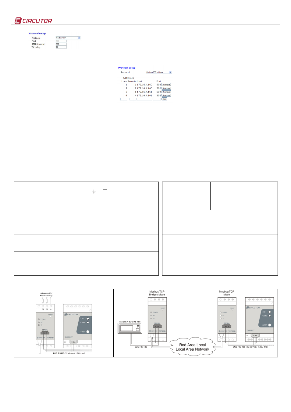
- Protocol: Modbus/TCP Mode
- Port: Fixed port number 502
- RTU timeout: maximum bus waiting time
- TX delay: additional delay on serial RS bus
2.3.4.- Modbus Protocol/TCP Bridges (routing)
The purpose of this work mode is to implement RS-
485 or RS-232 networks over existing Ethernet
network infrastructures, either Local Area Networks
or remote networks.
In the Modbus/TCP Bridges mode the unit performs
a constant supervision of the Modbus RTU frames
received through the serial port of the
TCP2RS+, and
its function is to address the frames in accordance
with the features programmed in the unit's
configuration web menu.
To do so, the master
TCP2RS+ must be configured
with the Modbus Protocol/TCP Bridges, as shown in
Figure 2. Its purpose is to address the frames
received through the RS port, depending on the node
number and destination IP at which the Modbus
sentence is sent.
The paths must be loaded into the device before
performing the addressing operations.
The slave
TCP2RS+ device(s) must be configured
with the standard procedure in the Modbus/TCP
protocol, with the serial port communications
parameters and in accordance with the equipment
that is physically connected to the RS-232 or RS-485
communications bus (speed, parity, data bits and
stop bit).
2.3.4.1.- Loading path to the master equipment
In the case of RS-232 or RS-485 topologies over
Ethernet networks, the paths being addressed must
be loaded to the master, according the Modbus®
node number.
List of routes
TCP2RS+ can be used to address the node
numbers. In some cases, the slave equipment
located in different Ethernet networks and connected
to different
TCP2RS+ can have a peripheral number
parameterised that is the same as other devices in
other IP networks.
To make sure that the user does not have to change
the node numbers,
TCP2RS+ can convert the node
number in the Modbus frame, replacing the local
node number issued by the communications master
number with the real node that the equipment has
available.
In the
List of routes, in the example of the Local
node No. 3, how the master sends the Modbus
command for node 03 and
TCP2RS+ replaces node
03 with node 01 in the Modbus/TCP frame, sending
the Modbus command to the slave
TCP2RS+
converter with 172.16.4.161. Even when there is a
different node number that is identical to that of bus
IP 172.16.4.160 (first path position),
TCP2RS+ routes
the information in accordance with the node number
and Ethernet address (IP) previously loaded to the
device.
- Local Address: Local node in the master
- Remote Address: Real node in the slave
- Host: IP of the destination or slave
TCP2RS+
- Port: IP Port of the destination connection (502)
2.3.4.2.- Parameterisation of IP connection ports
Modbus/TCP works in the fixed mode with TCP port
number 502. For this reason, there may be a problem
when working in remote mode, with installations
where the connection is established through a router,
in which various communication buses may operate
in parallel to slave
TCP2RS+.
In the Modbus Bridges mode,
TCP2RS+ allows the
random parameterisation of the connection TCP port,
receiving the prior configurations on the router
connecting to the Internet. It is worth noting that, in
this mode, the routing functions would be carried out
by the connection router first, and then by the
configuration of the internal web menu of the device
(path load).
3.- TECHNICAL SPECIFICATIONS
Power circuit:
- Single-phase (A1 – A2) :
- Earth connection terminal:
- Frequency:
- Maximum consumption:
- Working temperature:
- Humidity (no condensation) :
85…264 V
ac
/ 120…300 V
dc
47…63 Hz
4.6 …7.5 VA
-10 …+60 ºC
5 … 95%
LED symbols:
- Flashing power LED
- Flashing RX
- Flashing TX
- Full/Half (left in RJ45)
- 10 M/100 M (right in RJ45)
Powered unit and CPU activity
Activity in the receipt of RS-485 / RS-232 frames
Activity in the output of RS-485 / RS-232 frames
Green: Full Duplex connection / Yellow: Half Duplex
Green: Speed 100 Mbps / Yellow: 10 Mbps
Mechanical features:
- Case material:
- Equipment protection degree:
- Dimensions (mm):
- Weight:
- Maximum operating height:
UL94 - V0 self-extinguishing plastic
IP 20
35.4 x 73 x 84.68 mm (2 modules)
120 g
2,000 m
Standards:
IEC 60664, VDE 0110, UL 94, EN61010-1, EN55011, EN 61000-4-2, EN 61000-4-3,
61000-4-11, EN 61000-6-4, EN 61000-6-2, EN 61000-6-1, EN 61000-6-3, EN 61000-4-5,
CE
Network interface:
- Type:
- Connector:
- Network Protocols - Accesses:
Ethernet 10BaseT / 100BaseTX self-detectable
RJ45
TCP / UDP / Modbus/TCP - HTTP
Safety:
Installation category Category III / EN61010 double-insulated electric shock protection
class II. The equipment must be connected to a power circuit protected with type gl fuses,
in compliance with IEC 269, or type M, with values from 0.5 to 1A. It must be fitted with a
circuit breaker switch or an equivalent device, in order to be able to disconnect the
equipment from the power supply grid. The minimum section of the power supply cable
shall be of 1 mm
2
.
If the equipment is not used according to the manufacturer's specifications, the protection
provided by the equipment may be compromised.
Serial interface:
- Type:
- Transmission speed (configurable):
- Data bits:
- Parity:
- Stop bit
RS-485 / RS-232 three wires (A/S/B) (RX/GND/TX)
4800, 9600,19200, 34800, 57600, 115200 bps
7, 8
No parity, odd, even
1 or 2
4.- CONNECTIONS
Figure 1. Standard connection of serial equipment
Figure 2. RS-485 Systems over Ethernet infrastructures (Modbus/TCP Bridges Mode)
5.- TECHNICAL SERVICE
If you have any doubts about the operation of the unit or suspect any malfunction, contact our service staff at CIRCUTOR, SA
CIRCUTOR, SA - Technical Assistence
Vial Sant Jordi, s/n
08232 – Viladecavalls (Barcelona), SPAIN
Tel: (+34) 93 745 29 00 /
email: