Figure 7 – CIRCUTOR OPTIM P&P Series User Manual
Page 14
Advertising
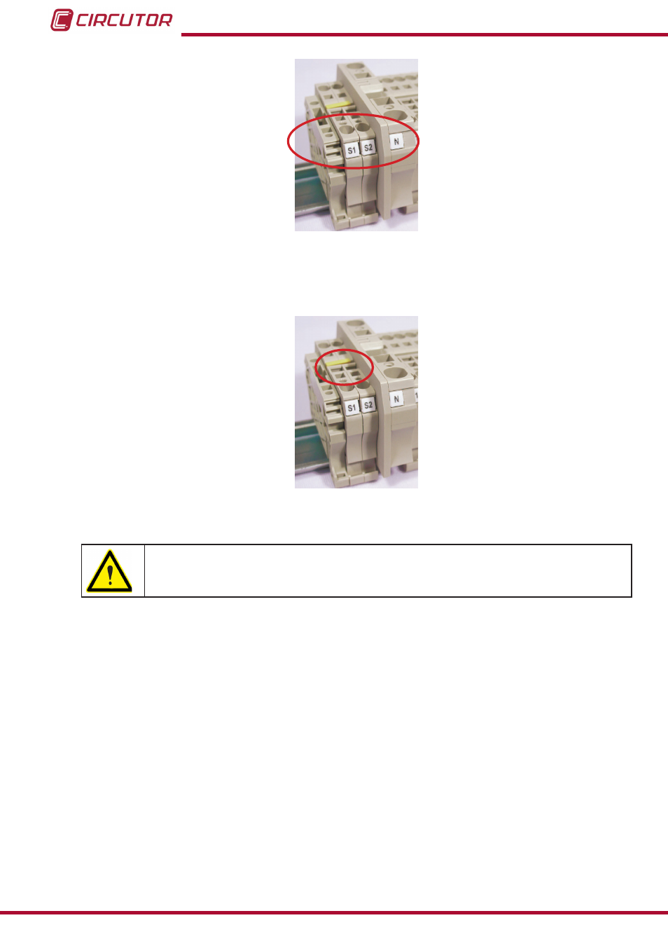
Figure 7: Current transformer (CT) and neutral connection terminals (if required).
Once the cables are installed, disconnect the jumper connecting the S1 and S2 terminals or the
yellow jumper according to the terminals of the capacitor bank (
Figure 8: Jumper for short-circuiting the secondary winding of the current transformer (CT).
Any time you wish to change or disconnect a current transformer that is already
installed, it is important to install the jumper connecting S1 and S2.
14
OPTIM P&P Series
Instruction Manual
Advertising