CIRCUTOR OPTIM P&P Series User Manual
Page 16
Advertising
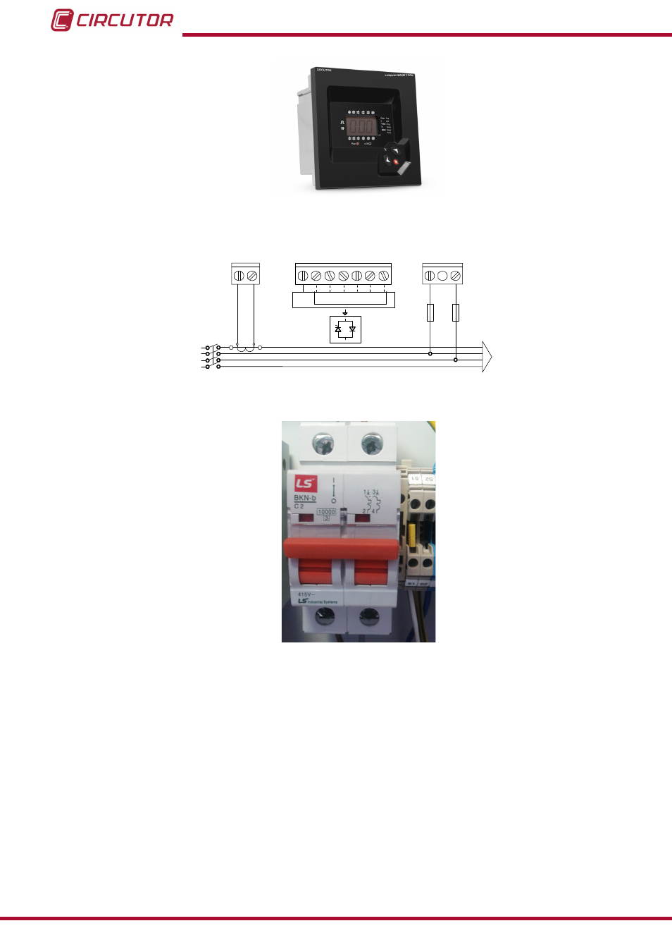
Figure 9: Plug&Play Computer Max Regulator. (Photo as an example, it may not coincide with the model used on
your unit).
-
+ C1 ... C6
-
L1
L2
L3
N
POWER
SUPPLY
0
1 2 3 4 5 6
400 V ac
A B
P1
P2
S1
S2
C
D
Figure 10: Connection of a regulator with only one CT. (If using Computer SMART III or Computer Plus, 3 CT are
used. Check the specific manual. )
Figure 11: Two-pole circuit breaker for the auxiliary power circuit.
4.- Once ensured that the regulator is properly connected, adjust the regulator parameters for
the installation you are attempting to compensate. For this, follow the instructions on the man-
ual of the regulator, included with the capacitor bank.
16
OPTIM P&P Series
Instruction Manual
Advertising